
Introduction to Antenna
Antenna is an electrical device which converts electric power into radio waves, and vice versa, antenna are used not only on radar but also on jammers, RWR and communication system .The function of the antenna during transmission is to concentrate the radar energy from the transmitter into a shaped beam that points in the desired direction. During the reception, or listening time, the function of the antenna is to collect the returning radar energy, contained in the echo signals, and deliver these signals to the receiver. Antennas are often distinguished by their beam shape and efficiency.

Dipole antenna

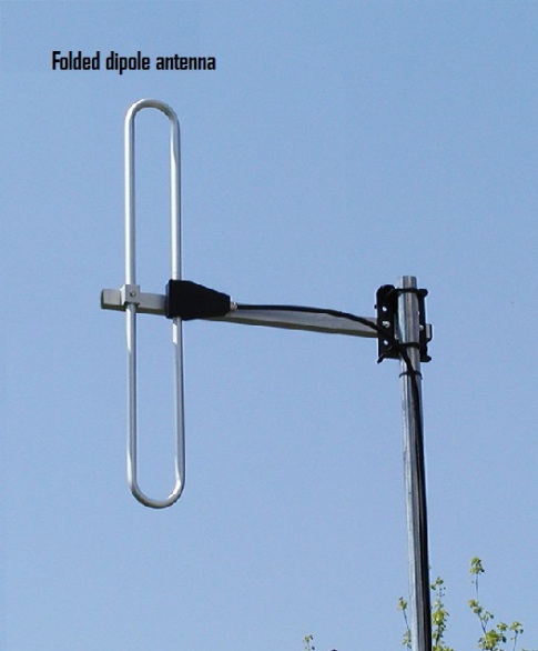
A dipole antenna or doublet is the simplest and most widely used class of antenna.It consists of two identical conductive elements such as metal wires or rods, which are usually bilaterally symmetrical.The driving current from the transmitter is applied, or for receiving antennas the output signal to the receiver is taken, between the two halves of the antenna. Each side of the feedline to the transmitter or receiver is connected to one of the conductors. Dipoles are resonant antennas, meaning that the elements serve as resonators, with standing waves of radio current flowing back and forth between their ends. So the length of the dipole elements is determined by the wavelength of the radio waves used.
- Radiating pattern
Dipoles are Omni-directional antennas. Thus, they are often used in communication systems.

Monopole antenna


A monopole antenna is one-half of a dipole antenna, mounted perpendicularly over some type of conductive surface, called a ground plane.The directivity (gain) of a monopole antenna is twice the directivity of a dipole antenna of twice the length because no radiation occurs below the ground plane; hence, the antenna is effectively twice as “directive”, due to higher directivity a monopole antenna can transmit wave further distance with similar transmitting power.
- Radiating pattern


Yagi-Uda Antenna

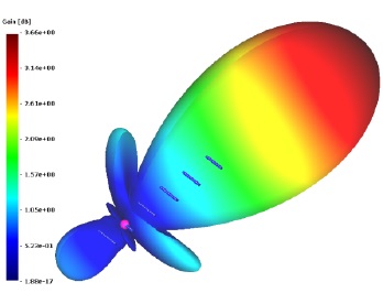
Yagi antenna is a directional antenna consisting of multiple parallel elements in a line. They often consist of a single ‘feed’ or ‘driven’ element, typically a dipole or a folded dipole antenna. This is the only member of the above structure that is actually excited (a source voltage or current applied). The rest of the elements are parasitic – they reflect or help to transmit the energy in a particular direction. The feed antenna is almost always the second from the end, as shown in the photo below. This feed antenna is often altered in size to make it resonant in the presence of the parasitic elements (typically, 0.45-0.48 wavelengths long for a dipole antenna).The element to the left of the feed element is the reflector. The reflector element is typically slightly longer than the feed element. There is typically only one reflector; adding more reflectors improves performance very slightly. This element is important in determining the front-to-back ratio ( gain in the maximum direction to that in the opposite direction ) of the antenna.The elements to the right of the feeder element are director elements, they are often slightly shorter than the feed element.Yagi antenna has very narrow operating frequency range and often have a maximum gain limit of around 17 dB.

- Radiating pattern

Corner reflector antenna

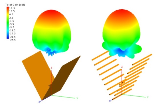
A corner reflector antenna is a type of radar antenna often used for VHF and UHF frequencies transmitters. It consists of a driven element ( could be a dipole or Yagi array ) mounted in front of two flat rectangular reflecting screens joined at an angle, usually 90°. The reflecting screen could be a sheet of metal or grid element ( for low-frequency radar ) to reduce weight and improve wind resistance of the structure. Corner reflectors antenna have a moderate gain of 10-15 dB and wide bandwidth.
- Radiating pattern
Log-periodic Antenna (LPDA)
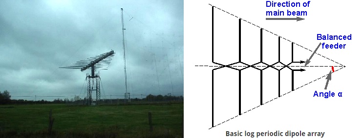
Log-periodic dipole array consists of a number of half-wave dipoles driven elements of gradually increasing length, each consisting of a pair of metal rods. The dipoles are mounted close together in a line, connected in parallel to the feedline with alternating phase.Even though log periodic is similar to multi-element Yagi designs in appearance, they work in very different ways. Adding elements to a Yagi increases its directionality (gain), while adding elements to an LPDA increases its frequency response (bandwidth), extremely wide operating frequency is also one of the main advantages of LPDA over others kind of antenna.The length of element on LPDA are related logarithmically, the length of the longest element is 1/2 of the wavelength of lowest frequency, and the length of the shortest element is 1/2 of the wavelength of highest frequency
- Radiating pattern

Helical Antenna

A helical antenna is an antenna consisting of a conducting wire wound in the form of a helix. Normally, helical antennas are mounted over a ground plane. The feed line is connected to the bottom of the helix and the ground plane. Helical antennas can operate in one of two principal modes — normal mode or axial mode.
- Normal mode/broadside helix: the dimensions of the helix (the diameter and the pitch) are small compared to the wavelength of transmitting frequency. The antenna acts similarly to an electrically short dipole or monopole, and the radiation pattern, similar to these antennas is omnidirectional, with maximum radiation at right angles to the helix axis. The radiation is linearly polarised parallel to the helix axis. These are used for compact antennas for portable and mobile two-way radios
- Axial mode/end-fire helix, the dimensions of the helix are comparable to the wavelength of transmitting frequency. The antenna functions as a directional antenna radiating a beam off the ends of the helix, along the antenna’s axis. It radiates circularly polarised radio waves. These are often used for satellite communication.
- Radiating pattern

Rhombic antenna
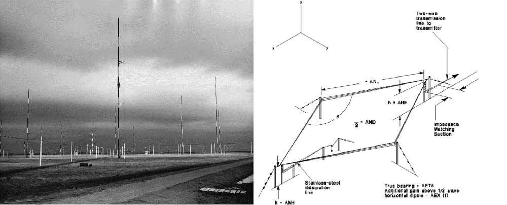
A rhombic antenna is a broadband directional wire antenna that consists of one to three parallel wires suspended above the ground in a rhombic (diamond) shape, supported by poles or towers at each vertex to which the wires are attached by insulators. Each of the four sides is the same length, typically at least one wavelength (λ) or longer.Rhombic antennas are often used for communication and work around HF band.
- Radiation pattern

Curtain Antenna

The curtain antenna is a multi-element dipole array, used in the shortwave radio bands (1.6-30 MHz ), it consisting of rows and columns of dipoles. The number of rows can be 1, 2, 3, 4 or 6; the number of columns is usually 2 or 4.The dipoles are horizontally polarised and a reflector screen is placed behind the dipole array to provide a directive beam.The number of dipole columns defines the azimuth beamwidth. For a 2-wide dipole array, the beamwidth is around 50°, for a 4-wide dipole array around 30°. The main beam can be skewed by 15 or 30° so that a maximum coverage of 90° can be achieved.

The number of dipole rows and the height of the lowest element above ground determine the elevation angle and consequently the distance of the service area. A 2-row high array has a typical takeoff angle of 20° while a 4-row high array has a typical takeoff angle of 10° .Radiation from curtain array often has very shallow approaching angle with the ionosphere , and due to the very low frequency , they are often reflected back to earth surface when they hit the ionosphere (skywave propagation ) , and since the radiation can hop multiple times between the ionosphere and earth surface , it is not affected by radar horizon .As a result, curtain array is often used in long-distance communication or over horizon radar
- .Radiating pattern

Horn Antenna


A horn antenna is an antenna that consists of a flaring metal waveguide that shaped like a horn to direct radio waves in a beam. Horn antennas have very wide operating bandwidth can be on the order of 20:1 ( for example : operating from 1 GHz-20 GHz) . Gain value of horn antenna can range between 10-25 dB , and they are often used as feed (transmitter) for larger antenna structures such as Parabolic or Cassegrain antennas
- Radiating pattern


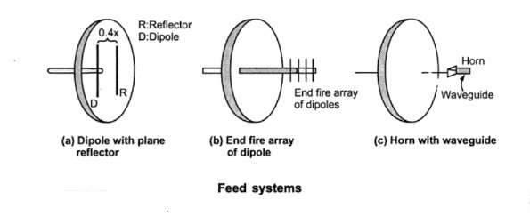
Parabolic Antenna

One of the most widely used radar antennas is the parabolic reflector.The parabola-shaped antenna is illuminated by a source of radar energy, from a transmitter, called the feed. The feed is placed at the focus of the parabola, and the radar energy is directed at the reflector surface.The most common kind of feed is horn antenna but it can also be a dipole or helical antenna
Because a point source of energy, located at the focus, is converted into a wavefront of uniform phase, the parabola is well suited for radar antenna applications. By changing the size and shape of the parabolic reflecting surface, a variety of radar beam shapes and radiating pattern can be created. Parabolic antennas have much better directivity characteristic compared to others kinds of antenna like Yagi Uda or Dipole, gain value can be as high as 30-35 dB. The main disadvantages of the parabolic antenna is that they are not suitable for low frequency due to their size. Another disadvantage of parabolic design is the feed can act as a blocker that obstructs the radar beam from the reflector.
- Radiating pattern


Cassegrain Antenna


A Cassegrain antenna looked very similar to a normal parabolic antenna but it uses a two-reflector system to generate and focus a radar beam. The primary reflector uses a parabolic contour, and the secondary reflector, or sub-reflector, has a hyperbolic contour. The antenna feed is located at one of the two foci of the hyperbola. Radar energy from the transmitter is reflected from the sub-reflector to the primary reflector to focus the radar beam. Radar energy returning from a target is collected by the primary reflector and reflected as a convergent beam to the sub reflector. The radar energy is reflected by the sub-reflector, converging at the position of the antenna feed. The larger the sub-reflector, the closer it can be to the primary reflector. This reduces the axial dimensions of the radar but increases aperture blockage due to the sub reflector. A small sub-reflector reduces aperture blockage, but it must be positioned at a greater distance from the primary reflector.Compared to normal parabolic antenna , advantages of Cassegrain antenna include: More compact ( even though Cassegrain antenna require a secondary reflector, the overall length of the dish antenna between the two reflectors is still shorter than the length between the feed and the reflector in normal parabolic antenna ) , reduce loss (because the receiver can be mounted directly near the feed horn) , less interference from side lobe for ground-based radar (even at high elevations very little spillover toward ground – all sidelobes point at cold sky ).These main disadvantages of Cassegrain compared to the parabolic antenna are: greater beam blockage ( the total size of the secondary reflector and the feed is larger than the feed in parabolic system ), not working well with board band feed.

- Radiating pattern

Gregorian Antenna


The Gregorian parabolic antenna is very similar to the Cassegrain design. The major difference is that the sub-reflector curved in the opposite direction from Cassegrain’s sub-reflector.Gregorian design often required smaller sub-reflector compared to Cassegrain antenna, thus reduce beam blockage.
Offset Antenna


As the name suggested, with this design, the feed and sub-reflector (in case of Gregorian type antenna) is offset from the centre of main reflector dish used, so that they will not block the radar beam.Offset design often used on Parabolic and Gregorian type antenna to improve their efficiency.
Twisted/Flat plate Cassegrain Antenna


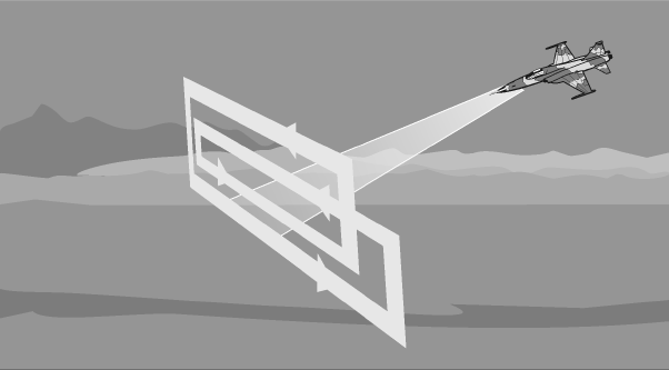
Another design that was developed to address the problem of sub-reflector blockage is the twisted Cassegrain antenna.This design work based on a simple principle of wave called polarization.An electromagnetic wave has 2 components ( magnetic field and electrostatic field ) that are always perpendicular to each other and perpendicular to the direction of travel.The polarization of the wave is defined by the orientation of the electrostatic field, polarization can either linear (vertical/horizontal) or circular ( left/right-hand-circular/elliptical ).The most interesting aspect of polarization is the polarizer or how to filter out a source so that the outcome polarised only in certain direction/plane .Typically polarizer made from a piece of material with atoms arranged parallel or it could also be a parallel wire screen with the distance between the wires less than the wavelength of the radio wave that needed to be polarised, a rule of thumb for the allowed gap is usually about haft a wavelength.) .A very common misconception is that electromagnetic wave and polarizer behave in similar fashion with a wiggling piece of string and a fence such as a horizontal polarised electromagnetic wave will be blocked by a screen with slit oriented vertically. This misconception is depicted in the photo below:

In reality, electromagnetic wave behaves very different from mechanical waves, the assumption that waves slip through the gaps between the wires is simply wrong.A plate made of parallel wire mesh oriented horizontally wire will completely block and reflect horizontally polarised radio wave while letting the vertically polarised wave pass through with little obstruction and vice versa. The reason for this is: when the electric field of a wave is parallel to the wire it will excite the electrons along the length of the wire ,since the length of the wire is many time its width electrons can move a lot and absorb most energy from the wave ,the movement of electrons will induced a current , this current will create it’s own wave. The secondary wave produced by induced currents will cancel the incident wave on the transmission side and behave as a reflected wave on the incident side of the surface. On the other hand, when the electrical field of a wave is perpendicular to the wire, it will excite electrons along the width of the wire and because electrons cannot move very far across the width of each wire little energy will be reflected. EM wave polarization is depicted in the photo below:

It is important to note that, even though most imagines illustrate radio waves often shown only 1 magnetic field and 1 electric field, that does not mean that their electronic/ magnetic field only oscillate in that exact plane. In fact, both electrostatic and magnetic field can be thought as made of sub-electrostatic/magnetic fields that are also perpendicular to each other, and they will add like vectors. For example: for a vertically polarised wave, it mean that the resultant electronic field ( vectors ) of 2 sub electronic fields is vertical. When the 2 sub-electronic fields are in phase ( having the same peak and trough ) then the resultant electronic field will always be stationary in one plane. However, if one of the sub-electrostatic fields is slower than the other then the resultant electronic field ( their sum vectors ) will start to spin around the direction of travel of the wave (this is often called elliptical polarization). If one sub-electrostatic field is slower than the others by exactly a quarter wavelength ( also known as 90 degrees phase different ) then we will have circular polarization wave as depicted in the photo below:

To convert linear polarised to circularly polarised wave and vice versa, we need to slow down one sub-electronic field more than the other by exactly a quarter a wavelength.To do that the most common option is to use a parallel arranged wire grid with the distance between each wire is about 1/4 wavelength and put it at an angle so that the wires making a 45 degrees angle with horizontal axis, this specific device is also called a quart-wave plate.A linear polarised wave hit a quart wave plate will be transformed into circular polarised wave while a circular polarised wave hitting a quart wave plate will be transformed into linear polarised wave.

Based on polarization principal, a flat plate Cassegrain antenna consists of 2 reflectors of equal size. The sub-reflector reflects only horizontally polarised waves and let vertically polarised one pass through. The primary reflector reflects all waves. The sub-reflector is a flat plate is placed in front of the primary reflector instead of a hyperbolic metal reflector. The sub-reflector consists of 2 parts, the first part is a plate with slits at an angle of 45° and the second part is a plate with horizontal slit, the slits are less than a 1/4 wavelength apart.

The basics principal is simple, For example: let say a left-hand circular polarised wave was transmitted from the feed. The wave passes the quart wave plate first and is transformed into a horizontally polarised wave. This wave will be reflected on the horizontal strained wires. The wave passes quart wave plate again but from the other side. The orientation of the fins is mirrored now and appears rotated by 90 degrees. This has the effect, that the former change of polarization is rescinded. Therefore, a left-hand circular polarised wave travels back to the primary parabolic reflector.The reflection on the primary parabolic reflector will change the left-hand circularly polarised wave to a right-hand one. After passing the quart wave plate a third time, this right-hand circular polarised wave will become a linear vertically polarised wave. This one can cross the horizontal slit sub-reflector without interaction and is emitted therefore vertically polarised toward targets ( opposite thing happened in receive mode ).
Slotted Antenna


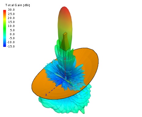
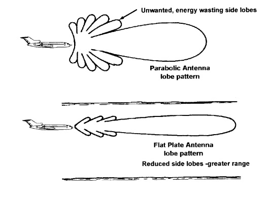
While Parabolic, Gregorian and Cassegrain antennas all have very high gain ( small main beamwidth) relative to aperture size. However, they all share the same disadvantages include: high sidelobes (make radars susceptible to low RCS targets and ground clutter) , reduced efficiency due to beam blockage ( beam blockage is a big problem for small radar such as the one on air to air missiles, offset design reduce this problem but they occupied bigger space thus not suitable for airborne application ).Due to problems stated earlier, a new antenna design called slotted arrays was developed. A slot array consists of a metal surface, usually a flat plate, with a hole or slot cut out. When the plate is driven as an antenna by a driving frequency, electromagnetic waves are emitted from each slot, one can understand each slot act as a small antenna and together they form an array.Since the beam from each individual slot is weak their side lobes are also very small Main characteristics of slotted arrays are high gain, low side lobes and light weight.
- Radiating pattern

Passive Electronically Scanned Array (PESA)


One problem that has been haunting radar designer since the early day of radar development is how to balance between radar accuracy, range and scanning time. This problem arises from the fact that a radar with narrower beamwidth will have better accuracy (resolution cell) and can look further with same transmitting power ( power more concentrated ).However, the narrower the radar beamwidth, the longer it would take for the radar to finish scanning its full field of view. Moreover, higher gain radar ( narrower beamwidth ) would require much bigger antennas which are unsuitable for fast scanning (To achieve useable accuracy at low-frequency, radar would require antennas of enormous size which could be impractical to even steer around by mechanical mean). One design that was created to address this problem is passive electronically scanned array (PESA). Instead of relying on mechanical mean, PESA relying on a phenomenon called wave interference to steer the radar beam.Wave interference is the phenomenon that happened when two or more waves of a same kind oscillate and meet at the same point in space , the total amplitude of these waves at that point will add up in a similar way to water ripple, depending on the exact phase different of these waves , the interference could either be constructive or destructive (as depicted in photo below) .
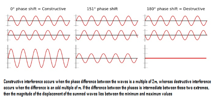
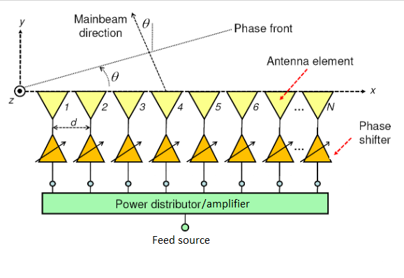
By controlling the phase different of a group of transmitting elements, the place where destructive and constructive interference occurred can be controlled thus, a beam can be formed and steered electronically. It is important to remember that, since PESA radar steers their beam by electronic interference, the minimum number of transmitting elements required for beam steering side to side on one plane is 2 ( For example: an array consists of a single horizontal line of transmitting elements will not be able to steer its beam vertically ) 

Typically , a PESA radar consists of 1 feed source , 1 low noise amplifier , 1 power distributor ,1 duplexes, around 1000-2000 transmitting elements and an equal number of phase shifters depending on the size and performance requirements of the radar
 Transmitting elements for PESA radar can be any kind of isotropic or directional antennas. Some common kind transmitting elements are as follow:


The most commonly used radiating antenna on the first generation of fighter active/passive phased arrays radar is patch antenna because they are the easiest to design

Modern active phased array moving toward Notch radiator due to their wide band characteristics and better gain than patch antenna:

Regardless of the kind of antenna elements used, more radiating elements will improve the directivity characteristics of the radar


As we learned before, if the operating frequency (wavelength) of radar stayed the same, bigger transmitting aperture will result in narrower beamwidth which will improve both range and accuracy of the radar system. However, for any phased array systems, it is not a good idea to increasing the spacing between radiating elements in an attempt to increase the aperture of the radar while keeping cost down. Because when the spacing between radiating elements is bigger than operating frequency, grating lobes will appear which will decrease radar performance significantly.


The most important and costly part of PESA radar are the phase shifters, without them, the phase of the signal cannot be controlled thus the beam cannot be steered.


There are many kinds of phase shifters, but they can generally be divided into 4 main kinds:
Delay-Switched Line /Time Delay Phase Shifter

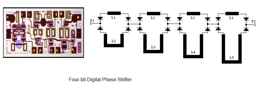
This is the simplest type of phase shifter. It will take time for the signal to pass through a length of transmission line. This time delay (equates to a phase shift of the signal) depending on the physical length of the transmission line, the frequency of the signal and the phase velocity of signals in the transmission line medium. By switching a signal between two or more pre-determined lengths of transmission line the phase shift can be controlled.Delay line approach is the most straightforward approach because it uses the simple time delay difference between two direct paths to provide desired phase shift. The switching elements in digital phase shifters are: mechanical switches (or relays), PIN diodes, Field Effect Transistors (FET), or micro electro mechanical systems (MEMS). PIN diodes are commonly used in delay phase shifters due their high speed switching time, low loss, and relative simple bias circuits, which provides changes of PIN resistance approximately from 10 kilo-ohms to 1 ohm.

The problem with this kind of phase shifters is that their phase error increase as frequency increased and their size increase as frequency decreased, moreover the phase change also varied with frequency (thus not suitable for frequency too high or too low ).
- It is important to remember that time delay phase shifter is not the same thing as true time delay device/time delay unit even though they based on the same principal ( a multi-path structure). A time delay phase shifter usually provides a fixed insertion phase difference between two states (flat phase over frequency). The two states have very small different in time delay (the two states differ in path length by less than a wavelength). On the hand, a time delay unit can provide many, many wavelengths of phase shift.Because the normal phase shifter do not provide proper different in time delay, the beam will be distorted over frequency (For example if the array diameter is 1 meters, a delay of at least several nano seconds is required), hence, true time delay unit are used to reduce this problem. Unlike phase shifters which are used at elements level, time delay units are used at sub-array level.
Reflective/Quadrature Phase Shifter
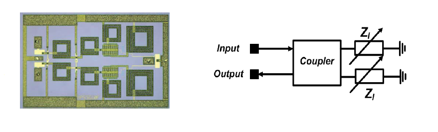
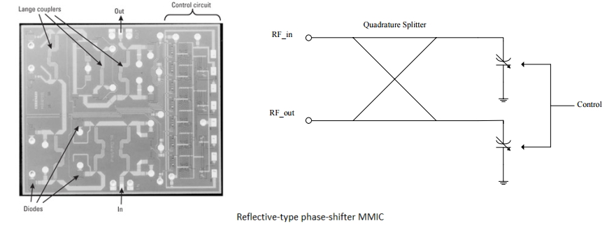
This kind of phase shifter is mainly a quadrature coupler which splits the input signal into two signals 90° out of phase then these signals reflect from a pair of switched loads .After that they will be combined in phase at the phase shifter output, as long as the loads are identical in reflection coefficient (both magnitude and phase). This phase shifter takes advantage of the phenomenon that reflections of signals on conducting lines can exhibit a phase change from the incident signal. The phase shift of the reflected voltage wave, compared to the incident, varies from 0° (open circuit – zero varactor capacitance) to -180° (short circuit – infinite varactor capacitance).Phase shifters of this type have been demonstrated with wide operating bandwidths. However, physical limitations of the varactors mean that the maximum phase shift which can be achieved in practice is limited to around 160° (with that being said, a number of such circuits can be combined if a wider range of phase shift is required ).
I-Q Vector Modulator


Similar to reflective phase shifter, in this kind of phase shifter an RF signal incident on a 3 dB quadrature hybrid is divided into two equal outputs, with a 90-degree phase difference between them. The in-phase or 0-degree channel is designated the I channel and the quadrature or 90-degree channel is designated the Q channel. Each signal then passes through a biphase modulator which has the ability to provide phase shift for the signal ( normally a small reflective phase shifter are used as biphase modulators) .A 0° or 180° phase shift is then applied to each signal, allowing the selection of any pair of quadrature vectors. Then the two signals are recombined using an in-phase combiner.Because the attenuation of both I and Q component can be controlled, the out put signal can be controlled not only in phase but also in amplitude.
High Pass-Low Pass/Switched Filter Phase Shifter
 Since delay line phase shifter can not provide constant phase shift over a wide frequency range, switched filter phase shifter was created.This kind of phase shifter works by switching the RF signal path between a high pass and low pass filter. In general , this kind of phase shifter is similar to delay line phase shifter, but the transmission lines are replaced by filters.A low pass filter consists of series of inductors and shunt capacitors that will provide phase delay to signal passing through it. A high-pass filter consists of series of inductors and capacitors that will provide phase lead for signal passing through it. Unlike delay line phase shifter, high pass -low pass provide very consistent phase shift for within its wide range of operating frequency. Moreover, the overall size of a switched filter phase shifter is considerably smaller than an equivalent switched line, reflective and I-Q modulator phase shifters, as a result, it is the most common kind of MMIC phase shifter for radar.
To sum up, compare to normal reflective antenna ,main advantages of PESA are as follow: extremely high scan rate ( improve the number of targets tracked, harder to be detected by RWR), time on target or dwell time may be optimised according to target type and requirements, high gain with low side lobes ( harder to jam , harder to detect and longer detection range), random scan pattern (harder to jam), specialised detection and modulation techniques may be used to assist in extracting target signals from noise. Main disadvantages of this kind of radar are higher cost and inability to scan pass 60 degrees broadside (Field of view of a stationary phased array accounted for a total of 120 degrees sectors, while mechanically scanned radar can have total FoV of 360 degrees ) due to mutual coupling problem.
Active Electronically Scanned Array (AESA)


From outside AESA and PESA are rather indistinguishable but their inner components are very different. PESA use a single or sometimes two high power amplifier (HPA) source ( often a klystron or traveling-wave tube ) transmitting a single power signal, the signal is then divided into thousands of paths represent thousand phase shifter and elements , there is also a single low noise amplifier (LNA), by contrast, AESA radar consist of thousand of transmit – receive modules The fact that the transmitter resides in the elements itself means there is no standalone transmitter and receiver – there is an exciter but that is all.Their main architecture differents is shown in photos bellow:

As can be seen from the diagram above, for AESA, most components such as low noise amplifier, high power amplifier, duplexer, phase shifter are miniaturized and put in a box called T/R modules, each individual T/R module on their own can be thought as a tiny radar. The architecture of a T/R modules can be seen in diagram bellow:

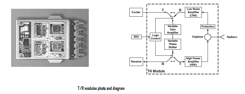
T/R modules count can often be used to estimate radar performer, some common AESA radar and their elements count are as follow:

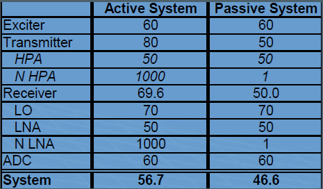
Even though both PESA and AESA uses wave interference to form and steer their beam, the unique design of AESA give it many advantages over PESA design. To begin with, in AESA design, the low noise amplifier is put near the receiver, before the lossy components, thus AESA radar can achieve better signal to noise ratio compared to PESA (better signal to noise ratio will improve radar detection sensitivity):


Secondly, in a normal radar system, the capability to reduce clutter interference is often limited by hardware instability errors such as pulse to pulse phase/amplitude errors and intra-pulse noise. Main contributors to these errors are analog-digital converter (ADC) ,down-conversion 1st Local Oscillator (LO), high-power amplifiers (HPA), low-noise amplifiers (LNA) and exciter/waveform generator. An AESA system has a distributed group of HPA and LNA, thus errors can be decorrelated. Better clutter attenuation capabilities mean AESA system will have better detection sensitivity in the presence of clutter.
Moreover, with equal detection performance, an AESA system often have higher duty cycle and lower peak power than a PESA system, hence better low probably of intercept characteristics.
Last but not least, since individuals T/R modules on AESA do not rely on a single high power amplifier, they can transmit signal at different frequencies at the same time. As a result, an AESA can form several independent beams at different frequencies simultaneously by dividing the array into a few smaller sub-array, that improves its multitasking ( For example: performing TWS and SAR at the same time ) and ECCM capabilities significantly over PESA system. Ability to operate at several frequencies simultaneously also permits electronic countermeasures (ECM) techniques to be employed anywhere within the field of regard of the array.However, it is important to note that forming too many different beams will also reduce radar range.

The 2 main disadvantages of AESA radar are very high cost and inability to scan pass 60 degrees broadside.
Hybrid ESA – Mechanical (movable AESA, PESA )


While having lighting fast scan rate, the main disadvantage of PESA AESA is their limited field of regard of only 120º in total. Thus, to solve that problem, on some modern radar, they put the PESA, AESA array in front of a repositionable disc to increase the field of regard of the radar. Radar field of regard should not be confused with radar beam width. Radar beam width referring to how wide/narrow the radar beam is, which is also the angular cone perceivable by the radar at a particular time instant. On the other hand, radar field of regard referring to the total size of space in degrees that can be captured by a movable/steerable radar. Narrow beam width is often desirable for better accuracy and detection range, narrow field of view is not desirable.

Radar Lobes
It has been explained earlier that reduce sides lobes will improve radar range, “so what is radar lobes ?” you may ask.
As we already know, the narrower the radar beam is, the further it can look and the more accurate the system would be. However, even the most directional radar cannot focus all its power into a single beam. In fact, radar power often split into several parts, also called lobes.


Main lobe: is the region around the direction of maximum radiation (usually the region that is within 3 dB of the peak of the main beam) where the radar has the most power and where target detection occurs.
Side lobes: are smaller beams that are away from the main beam. These sidelobes are usually radiation in undesired directions
Back lobes: are side lobes that are in opposite direction with the main lobe.
Half power beam width/ -3dB beam width: is the angular separation in which the magnitude of the radiation pattern decrease by 50% (or -3 dB) from the peak of the main lobe
Nulls: place where power of radiation pattern decreased to zero due to destructive interference
- Generally, the radiated power in side lobes and back lobes are a lot weaker than in the main lobes, the power different could be around 40-50 dB
- The side lobes (normal characteristic of all radars system) is not the same as the ability to form multiple beams for different roles (which is unique to AESA system ) even though they both split total radar power into several parts, the reason being that side lobes will have exactly the same frequency, same polarization , same PRF as well as the pulse duration as the main lobe .Thus, it is not possible for radar to distinguish between the radar return due to side lobes and radar return due to main lobes. On the other hand, AESA can form several beams that work at different frequencies, different PRF and different pulse duration allowing the processor to distinguish the returns that resulted from different beams.
- In receiving phase the unwanted received energy outside the main lobe is also called side lobe
Despite much weaker radiating power compared to the main beam, return from side lobes still reduce radar ability to detect targets. Because when the main beam pointed at the horizon, a significant part of side lobes pointed at ground, result in a lot of clutter , even though the side lobes power is weaker ,the ground is often much closer to the aircraft radar compared to the threat aircraft ,thus their return can be equal and similar in power. Because the surface is generally stationary, one way to reduce the problem of side lobes is Doppler processing (clutter problem due to side lobes can not be solved by increasing radar transmitting power), however, side lobes clutter still cause a lot of problems in detecting fleeing targets that have similar speed as the chase aircraft.

Side lobes also make radar more detectable because the side lobes may still point at target even when the main lobe is pointed at different direction.Thus, a high power sidelobes will not only alert targets that haven’t been detected by the main beam yet, it also give adversary ESM/RWR significantly more time to analyze radar emission and geolocate radar location. 
Radar Search/Scan Pattern
Scan pattern referring to how radars steer their beam across their field of view to search for targets
Circular Scan
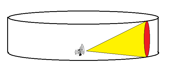
In circular scan pattern, this scan pattern is very common among ground early warning radar because it allows the radar to scan large volumes of airspace for early target detection. To perform this scan pattern the antenna generates a fan beam that has a large vertical beamwidth and a small horizontal beamwidth then the radar continuously scans through 360° in azimuth.This scan pattern can provide target range and azimuth information but not target altitude.
Helical Scan

This scan pattern is very similar to circular scan pattern but often used in high gain (pencil beam) radars. For this pattern, the antenna sweeps a 360° sector in a clockwise direction. After each complete revolution, the antenna elevation is increased. This scan pattern is repeated for a specified number of revolutions. At the end of the scan pattern, the antenna elevation is reset to the initial elevation and the scan is repeated. Helical scan pattern is commonly used as a target acquisition mode for ground fire control radar.
Raster Scan
For raster scan pattern, radar uses a thin beam to cover a rectangular area by horizontally sweeping the area. The angle of elevation is incrementally stepped up or down with each horizontal sweep of the desired sector. After the sector has been covered, the angle of elevation is reset to the original value and the process is repeated. The number of raster bars is set by the number of horizontal sweeps in the basic raster pattern. The photo above shows a four-bar raster scan.
Palmer-Raster Scan

This is a fusion of conical scan and raster scan.For this scan pattern, radar uses a thin beam, employing a spinning searching pattern for a specific sector of airspace. With each spin-sweep of the sector done, the angle of elevation is stepped up or down. After the whole field of view has been covered, the angle of elevation is set at the original elevation and the process is repeated.
Palmer-Helical Scan

This scan pattern is a fusion of helical scan and conical scan pattern. The radar uses spinning scan pattern to scan the azimuth horizon, after each complete revolution, the antenna elevation is raised.This scan pattern is repeated for a specified number of revolutions. At the end of the scan pattern, the antenna elevation is reset to the initial elevation and the scan is repeated.
- Phased arrays like PESA and AESA often have random, undefined scan pattern.
Target Tracking
Usually, after a target is detected, the radar is often be asked to : continues to “detect” the target as it moves through the radar coverage, use the available detection information develop a more accurate picture of the target position and predict where the target will be in the future. All these functions are also known as tracking During the pulsed radar tracking mode when the radar is locked on target, it follows and automatically maintains key data with respect to the target:
- Tracking in range
- Angle tracking in azimuth and elevation.
Range Tracking
Tracking in range is usually accomplished using a technique called range gating which automatically tracks the target as its range increases or decreases. The concept of the range gate is shown bellow:
![]()
The radar return in the region of the target return will comprise noise and the target return. The range gating technique uses two gates, an ‘early gate’ and a ‘late gate’. The early gate is positioned near the leading edge of the target echo and detects and captures energy from the early part of the target return. Conversely, the late gate is positioned near the trailing edge of the target echo and detects and captures the energy from the trailing edge of the target return. The detected signals from the early and late gate are compared and the result is used to position the tracking gate so that it is coincident with the target return.
Angle Tracking
During the radar tracking mode, the radar tracks the angle to the target in azimuth and elevation.There are three main methods of angle tracking that are commonly used, these are:
Sequential Lobing
The first angle tracking method adopted was sequential lobing. The principle of sequential lobing is shown in the photo bellow:

To track a target in one axis, two lobes are required; each lobe squints off the radar boresight. The centre point of where the two lobes overlap represents the boresight of the antenna and this is the tracking box that the radar antenna is trying to maintain. It can be seen that, when the signal return from the target is the same in both beams, the LOS to the target has been achieved. As the target moves, continual error signals will be sensed and the antenna servo system responds by nulling the error and keeping the target in the tracking box. If four lobes, A and B and C and D, are positioned as shown in the photo above, then lobes A and B provide tracking in elevation and lobes C and D provide tracking in azimuth. The reflected signal from the target received in each of the four lobes is routed via a channel switching assembly sequentially switched into the receiver. In this way, each of the four lobe returns is measured and error signals are derived to move the antenna. In practice, the waveguide switching arrangement is cumbersome and prone to losses ( four separate antennas or four separate feed horns are required in addition to very complex waveguide plumbing and switching techniques ). Therefore, radar performance is compromised. The other significant disadvantage suffered by this method relates to the time taken for the sequencing to occur. The radar PRF will determine the maximum time that the receiver will be switched to a particular lobe. Only when the radar has completed the range sweep for a particular PRF can the receiver sequence to the next lobe. Furthermore, the elevation and azimuth error can only be updated once per cycle, and this adversely affects update rate and tracking error.Sequential lobing can be detected and a target can use inverse gain jamming to break radar lock. Transmitting on all four beams and receiving only on one may counter this kind of jamming. This technique is called lobe on receive only (LORO).
Conical scan
A conical scan or con-scan tracking is is a development of the sequential lobbing scheme already described. For conical scan pattern, radar employs a beam of radar energy that is continuously rotated around the target. This circular rotation of a pencil beam generates a cone-shaped scan pattern with the apex of the cone located at the antenna. Thus, the name conical scan.As the radar beam rotates around the target, the circular scan patterns overlap in the centre. This creates a central tracking area that has a much smaller effective beamwidth than the rotating radar beam. This results in a very precise tracking solution.

However, similar to sequences lobing, the actual movement of the beam through space of conical scan tracking method is easily detected by the target. As a result, they can apply inverse gain jamming to break radar lock. This deficiency may be overcome by Conical Scan on Received Only (COSRO). In this mode, radar employs a non-scanning transmit beam from a separate antenna and a rotary (nutating) scanner in the waveguide between the duplexer and the receiver to extract elevation and azimuth angle error. The COSRO scanner has the effect of shifting the axis of greatest sensitivity to echo reception similar to the slight change in the direction of the transmitted beam of a conical scan radar caused by nutation (rotation) of the feed horn. You can imagine that a receive beam has similar shape to a transmitted beam, being nutated ( rotated) near radar boresight axis. RWR of the target being tracked by the COSRO radar would detect a steady, non-scanning, pulse radar beam that would provide no information that would assist in determining deception techniques beyond the normal radar performance parameters such as frequency, PRF and pulse duration.
Monopulse Tracking
Monopulse is the preferred tracking method of most tracking modern radars not only because it is very accurate but also because it is hard to deceive. The term monopulse means that a tracking solution may be determined on the basis of a single pulse rather than the beam sequence (sequential lobing) or a complete conical scan. The tracking data rate is therefore much higher and therefore potentially more accurate. Another advantage is that the tracking is based on the simultaneous reception of the target return in all four channels and any variation in the echo in time can be readily accommodated which is not the case with the other techniques.

The basic principal of monopulse is shown in the photo above, monopulse uses two to four simultaneous beams , in which the beams are stacked in elevation and side by side. Monopulse tracking techniques may use either phase or amplitude comparison to perform the tracking task.
For amplitude comparison monopulse, all four beams squint away from the antenna boresight by a small amount ( usually such that they overlap at the half power beam width point of the beam).The beams often have different polarization. When the reflected signals are received they are amplified separately and compared to each other, indicating which direction has a stronger return, and thus the general direction of the target relative to the bore sight.

For phase comparison monopulse, the system use 2 separate antennas (can be 4 antennas too ) and illuminate the same volume in space. Instead of being squinted like in amplitude comparison monopulse system, the beams are kept parallel in phase comparison monopulse system. Because the beams are parallel, if the target is at the centre, the radar reflection will arrive at the 2 antennas at the same time and has the same phase.On the other hand, if the target is at an angle to the bore sight then the radar reflection will arrive at one antenna later than the other.

In general, the main advantage of phase comparison monopulse is much higher accuracy while amplitude comparison monopulse has better signal to noise ratio.

Because monopulse tracking techniques required 2 or 4 separate radar beams, the radar system that can perform monopulse tracking need to have either several radar feeds or several antennas (or use an AESA system). Thus, increase complexity and cost of the system. Moreover, even through monopulse tracking is extremely accurate, it full performance can only be realised of when there is only a single target being tracked.When there are multiple targets within radar resolution cell or when there is multi-path reflection then monopulse tracking accuracy will degrade rapidly.

Radar Mode
Unlike ground system, that can afford to have different radars for different roles, airborne radars often have strict limitations in size and weight.Thus, for a fighter, her radar have to take on various jobs.As a result, software were developed to allow radars to operate in very different modes, each with unique PRF, scan sector and pulse duration so as to be best optimised to the specific job that they have to do at that moment. Here are some common radar modes.
Velocity Search (VS )

The PRF ( Pulse repetition frequency ) are set at maximum, higher PRF results in more power on target, more power mean more reflection, this mode is specifically for detecting medium and high closure targets, with the cost of not detecting low and no-closure targets at all. Velocity search mode displays targets on the radar screen by azimuth and velocity instead of by azimuth and range. in velocity search, many new pulses are sent before original pulse coming back.Thus, radar cannot determine the distance, as a result it can only be used for detection rather than tracking (or targeting ). Main advantage of velocity search mode is very long detection range, could be double of track while scan mode.
Range While Scan (RWS )
The system is set up so as to get quick target information at the expense of accuracy.The RWS mode provides all-aspect (nose-on, tail-on) and all-altitude (look-up, look-down) target detection. This is the most commonly used mode upon nearing a hostile environment. It is a good balance of wide volume and fairly rapid scan. This mode is used to resolve (detect) multiple targets separated by less than the antenna beam-width, at long range. There are three RWS modes, depending on what pulse repetition frequency ( PRF) is used for emitting radar energy. In RWSH mode high PRF is used, while in RWSM mode medium PRF is used. High PRF’s are better to detect distant contacts with high closure rates with the risk of low or no-closure contact not showing up on the radar screen. Medium PRF’s are not very good at long ranges since they are subject to clutter when receiving returns from long ranges, but they are useful for detecting medium-range low closure targets or targets which are below the radar water line. A good mixture of high and medium PRF’s is realised in RWSI mode (interleaved RWS) when the radar emits energy alternating between high and medium PRF’s as it scans through bars. RWS mode cannot be used to effectively to attack targets, but to get quick information about where the potential targets are. ,RWS is the most common mode
Track While Scan (TWS)

With the aid of sophisticated computer systems, multi-function radars are capable of simultaneously tracking many targets. In this case, each target is sampled once (mainly range and angular position) during a dwell interval (scan). Then, by using smoothing and prediction techniques future samples can be estimated.The mode that allow radar to perform multi-tasking and multi-target tracking are known as Track-WhileScan (TWS) radars. Once a radar in TWS mode detects a new target it initiates a separate track file for that detection; this ensures that sequential detections from that target are processed together to estimate the target’s future parameters. Position, velocity, and acceleration comprise the main components of the track file. Typically, at least one other confirmation detection (verify detection) is required before the track file is established. Unlike single target tracking systems, TWS radars must decide whether each detection belongs to a new target or belongs to a target that has been detected in earlier scans. And in order to accomplish this task, TWS radar systems utilize correlation and association algorithms. In the correlation process, each new detection is correlated with all previous detections in order to avoid establishing redundant tracks.Generally, in TWS mode the radar system places a gate around the target position and attempts to track the signal within this gate. The gate dimensions are normally azimuth, elevation, and range. Because of the uncertainty associated with the exact target position during the initial detections, a gate has to be large enough so that targets do not move appreciably from scan to scan; more precisely, targets must stay within the gate boundary during successive scans. After the target has been observed for several scans the size of the gate is reduced considerably
. TWS mode uses either high or medium PRF. In TWS mode the radar beam covers an area much smaller than the maximal 120 degrees, but this way the target updates are much quicker. It takes around 2 seconds for the radar to complete a full scan. The arc and number of bars covered by TWS scan can be set to different settings: ‘wide’ (60 degrees with 2 bars), ‘medium’ (30 degrees with 4 bars) and ‘narrow’ (15 degrees with 6 bars).
Single Target Track ( STT):

If the pilot marks a single target for tracking, then the radar enters STT mode and begins tracking that specific target. This tracking uses a 3 degrees mini-raster of radar energy centred on the target with very quick scans thus rapid target updates. Single target track mode often uses monopulse tracking techniques. (missiles launch is made in TWS or STT only).
Synthetic Aperture Radar (SAR) mode:

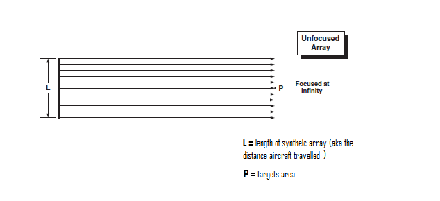
Apart from finding and attacking air targets, one very important job of fighter is to find and attack ground targets. The common sensors that are often used for this roles are RWR ( radar warning receiver ) and FLIR ( forward looking infrared ).But, the weather is not always good enough to allow the use of FLIR and enemy is not always transmitting to allow the use of RWR, thus, radars were adapted to ground attack role. One big problem with radar in ground attack role is that not only adversary tanks , trucks can reflect the radar signals, the ground surface can reflect radar signal as well so radar cannot rely on simple echo to find target like in air to air scenario. One solution is to use radars with very high resolution so that they can see targets in a similar way as an FLIR system. However, as we learned before radar resolution, aperture size and wavelength have very strong correlation. A radar that works at X-band ( common frequency for fighter radar ) that have beam width narrow enough to allow it to see the detail of ground targets would have to be too big that it would be impractical to for fighters to carry. On the other hand, a radar working at very high frequency can have very good resolution that will allow fighters to see ground targets very clear, but with such high frequency the radar beam will be attenuated too much by moisture and oxygen that they will not be able to see very far, hence not suitable for fighters. As a result, synthetic aperture radar (SAR) technique was created.In this solution the aircraft forward movement is used to create a large synthetic or artificial aperture, SAR works similar of a phased array, but contrary of a large number of the parallel antenna elements of a phased array, SAR uses one antenna in time-multiplex.The basic principal can be seen in the photo below:
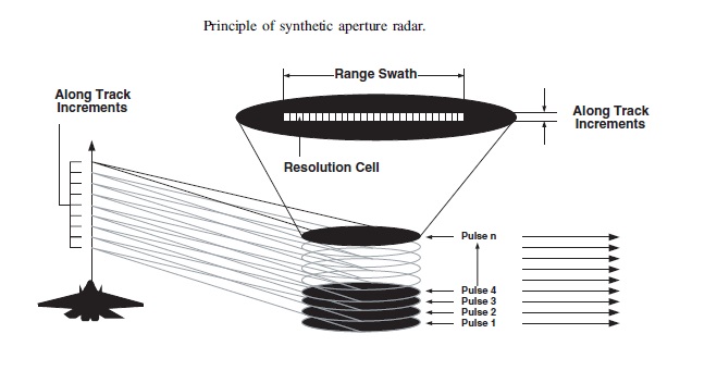

The aircraft shown on the diagram is transmitting a series of pulses at constant intervals to the side of its flight path, which equates in turn to constant along track increments. A series of patches of ground will be illuminated abeam the aircraft and the return from pulses 1; 2; 3; 4; . . . ; n may each be detected and collected in a series of range bins.The principle of this technique, easily implemented in a digital computer

After a series of pulses returns has been stored, the oldest are eventually discarded; the number of pulse returns retained before discarding is a function of the algorithm being used. This memory bank of the returns of the previous n pulses may be rapidly scanned to present a strip-line picture of the area of the terrain being mapped. This fairly crude SAR processing technique is referred to as an unfocused array SAR. The key point about the forward movement of the aircraft is that it allows the signal processing to synthesize an aperture much larger than the real aperture, the real antenna on the aircraft serves only as a single radiation element in a long linear synthetic array. In a typical unfocused array SAR application, an array length equivalent to 50m or more can be synthesized, and in this case, the azimuth resolution ( also known as cross range resolution) may be determined by the following approximate formula:


Whereas, the range resolution (also known as cross range resolution) is varied with pulse width (pulse length). For a 1ms pulse, the range may be resolved to 500 ft ( 150 m); for a 0.1 ms pulse this would be reduced to 50 ft ( 15 m); for a 0.01 ms pulse the resolution would reduce to 5 ft ( 1.5 m) and so on. So basically, a shorter pulse width is better for range resolution. However, pulse width of the radar is limited by hardware constraints and the amount of “energy on target” required to get sufficient signal-to-noise ratio to obtain a good image. In layman terms: long pulses have less resolution but have more energy to travel long distance. Whereas short pulses have high range resolution but often have very low energy.

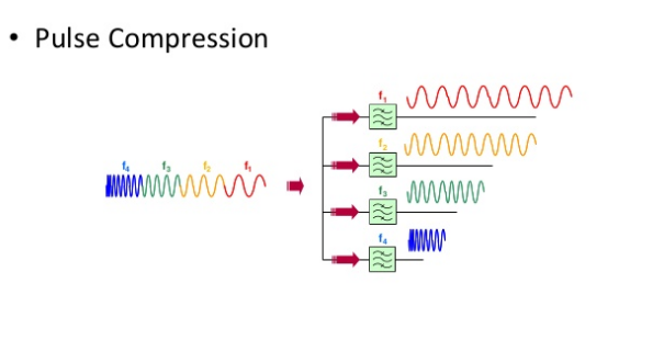
To achieve a high range resolution without a short pulse, frequency modulation can be used to synthesize an effectively short pulse. This process of generating a narrow synthetic pulse width is called pulse compression. The approach is to introduce a modulation on the transmitted pulse. Because the pulse is modulated internally, each part of the pulse has unique frequencies or phase so these returns can be completely separated (matched filter is used) and integrated into a shorter single output pulse. The most common transmit waveforms used for pulse compression are linear FM (or chirp) and phase coded. Some radars use a digital version of linear FM called a stepped frequency waveform. Due to pulse compression technology, the factor that limits down range resolution of SAR on modern radar is radar bandwidth rather than pulse width.

Even though very useful, Unfocused arrays SAR has a number of disadvantages. The most major one come from the fact that all of the pulses transmitted when SAR mapping being done are effectively parallel with each other instead of focusing at the target.
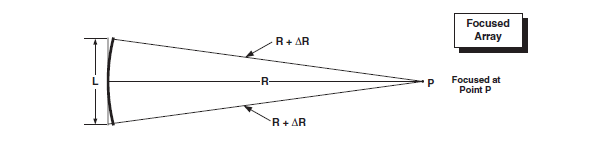
Because the range between the target area and the aircraft at different flying position along the synthetic length are not a constant, the range when the aircraft is at both end is greater than the range when the target is at the normal to the flight path. When the range different for aircraft at different position along the synthetic length is larger than a range resolution cell, it is called a range walk.

A range walk will cause the reconstructed imagine to be un-focused or obscure ( effectively limit the resolution of unfocused array SAR ).To prevent range walk from happening the range from every array point in the synthetic aperture to a fixed surface location can only differ by less than λ/8 ( with λ is radar wavelength). Thus the limit length for the synthetic arrays would be:
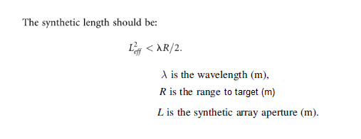
As a result, the maximum achievable cross-range resolution of the unfocused SAR is limited to:

The cross-range limitation of an unfocused SAR can be removed by focusing the data, as in optics. The focusing procedure for the SAR involves adjusting the phase of the received signal for every range sample in the image so that all of the points processed in cross-range through the synthetic array mode appear to be at the same range.
SAR mode with phase compensation is called focused array SAR mode. This mode required immense amount of processing power but the processing load can be reduced by the use of Doppler filters formed by Fourier transform. Focused SAR can achieve significantly better cross range resolution compared to unfocused SAR, moreover its cross-range resolution is also independent of range. It is also interesting to note that the maximum cross range resolution of focused SAR will get better if the length of the real transmitting antenna get shorter.

The diagram below show the comparison of maximum achievable azimuth (cross range) resolution between real beam, unfocused SAR and focused SAR. The radar is assumed to work at X-band, pulse length is 0.1 ft , and radar aperture is 10 ft long.

Apart from the common strip mapping mode, SAR mode also has several sub-modes:

-
Strip Mode
Common SAR mode with the beam fixed ,perpendicular to the flight direction
-
Spotlight Mode
This is a sub mode of SAR mode In the spotlight mode the look angle of the real antenna is altered so that it always illuminates the target. This has a number of advantages. Since the real antenna is always trained on the target, the length of the synthetic array is not limited by the beamwidth of the real antenna.Spotlight SAR is capable of extending the high-resolution SAR imaging capability significantly. As more pulses are used, the azimuth resolution increases. Also, the fact that the target is viewed from different aspects helps to reduce the graininess of the response.
-
Squinted Strip Mode
In most examples of synthetic aperture radar, the beam is directed at right angles to the ground track of the aircraft. In some cases, however, it is desirable to “squint” the antenna beam so that an area either forward or aft of the aircraft is mapped. It is necessary to position the antenna beam so that the maximum of its radiation pattern points in the desired squint direction. Moreover, it is usually necessary to modify the signal processors to take into account the average doppler frequency shift that occurs when the antenna points in a direction other than normal to the flight path. It is, of course, also necessary to take the geometry of the squint mode into account in designing recorders and displays
-
ISAR ( Inverse SAR ) Mode
Inverse SAR (ISAR) is a variant of SAR that is used against moving targets that have a rotational component; while normall SAR is used against fixed ground targets. ISAR effectively uses the minor Doppler shifts caused as a result of target movement. ISAR may be used against aircraft or moving ground targets such as ships .In ISAR, the target motion is often not known to the radar. Hence, a major part of the problem is determination of the target motion to generate the matched filter needed to generate an image.
-
MTI ( Moving Target Indicator ) Mode
In this mode radar uses Doppler filter to distinguish between stationary ground and moving ground targets. Because radar in MTI mode can not see stationary targets, structures and radar in SAR mode cannot see moving targets clearly. Thus, they are often used together.
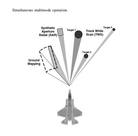
Multimode Operation:
Due to their ability to form multiple beams simultaneously, AESA radars (such as APG-81, APG-80, APG-77 ..etc ) can perform multi-mode at the same time:
Radar modes and their associated waveform parameters:


References:
- Chrzanowshi, E. J., Active Radar Electronic Countermeasures, Artec House,Inc., Norwood, MA, 1990.
- Skolnik, M. L., Introduction to Radar Systems, McGraw-Hill, Inc., New York, NY, 1980.
- Stimson, G. W., Introduction to Airborne Radar, 2nd Edition, SciTech Publishing, Inc., Mendham, NJ, 1998
- 4513 ATTG/INW, Advanced Radar Principles for Electronic Combat, 15 April 1991.
- Kayton, M. and Freid, W.R. (1997) Avionics Navigation Systems
- Wiley-Interscience. Lovell, B. (1992) Echoes of War – The Story of H2S Radar
- Adam Hilger. Pilot’s Handbook – Honeywell Radar RDR-4B.
- Alan J. Fenn, PhD MIT Lincoln Laboratory (14 January 2011)Antenna Design for the Laptop Radar Project
- The Basics of Antenna Arrays notes, 2010, Available: http://www.orbanmicrowave.com.
- Zooghby, A. E., Smart Antenna Engineering, Artech House, Inc., U.S., 2005.
- Balanis, C. A., Antenna Theory, Canada, A John Wiley & Sons, Inc., U.S, 2005.
- Agarwal, A. K. and E. L. Holzman, “Beamformer architectures for active phased-array radar antennas,” IEEE Transactions on Antennas and Propagation, Vol. 47, 1999.
- Kiuchi, E. and I. Ueda, Tactical cylindrical active phased array radar,” IEEE International Symposium on Phased Array Systems and Technology, 1996.
- Wang, D.-C.,”System analysis of wideband phased array radar,” Modern Radar, Vol. 30,No. 3, 1-6, 2008.
- Ekelman, E. P. and B. S. Lee, “An Array-Fed, Dual- Reflector Antenna System (of Offset Confocal Paraboloids) for Satellite Antenna Applications,” IEEE Symp. Antennas Propag., pp.1586-1589, 1989
- Johnson, R. C., and H. Jasik (Eds.), “Antenna Engineering Handbook”, 2nd ed., McGraw Hill Book Company, New York, pp. 32–11, 32–12, 1984.
- Holzman and A. Agrawal, “A comparison of active phased array, corporate beamforming networks,” IEEE Int. Symp. Phased-Array Technol., Boston, MA, Oct. 1996, pp. 429–434.
- “Radar Systems Engineering Lecture 8 Antennas Part 1 – Basics and Mechanical Scanning” Dr. Robert M. O’Donnell IEEE New Hampshire Section Guest Lecturer
- “Radar Systems Engineering Lecture 9 Antennas Part 2 – Electronic Scanning and Hybrid Techniques“Dr. Robert M. O’Donnell IEEE New Hampshire Section Guest Lecturer
- “Radar Fundamentals” Prof. David Jenn Department of Electrical & Computer Engineering
- Edwards, T.C. ”Foundations for Microstrip Circuit Design”, John Wiley & Sons Ltd, 1981. ISBN 0- 471-27944-7
- Ayasli, Y. “Microwave Switching With GaAs FETs”, Microwave Journal, Novenber 1982, pp. 61-74
- Krafcsik, D.M. et al, “A Dual-Varactor Analog Phase Shifter Operating at 6 to 18GHz”,IEEE Transactions on Microwave Theory and Techniques, Vol. 36, No. 12, December 1988, pp 1938-1941
- Tuckman, M. “I-Q Vector Modulator – The Ideal Control Component?”, Microwave Systems News, May 1988, pp 105-115
- Devlin, L.M. and Minnis, B.J. “A Versatile Vector Modulator Design for MMIC”, IEEE MTT Symposium Digest, 1990, pp 519-522
- Devlin, L.M. “Digitally Controlled, 6 Bit, MMIC Phase Shifter for SAR Applications”, Proceedings of the 22nd European Microwave Conference, 1992 pp 225-230
- “Electrically Tunable Switched-Line Diode Phase Shifters” – L. Maloratsky
- “Phase Shifters“Iulian Rosu available at http://www.qsl.net/va3iul/
- “Active Phased Array Radar Systems” Dr. Yasser Al-Rashid Lockheed Martin MS2
Radar Systems (November 17, 2009) - “Fundamentals of Phased Arrays“Parbhu D. Patel ASTRON, The Netherlands 26th November 2007
-
“Phase Shifters” available at http://www.microwaves101.com/encyclopedias/phase-shifters
- “The Cassegrain Antenna” available at http://www.radartutorial.eu/06.antennas/Cassegrain%20Antenna.en.html
- ” RFIC and MMIC Design and Technology” By I.D. Robertson, S. Lucyszyn, Institution of Electrical Engineers
- “Beamforming with a 20-Source Phased Array” available at http://www.in-node.com/page2.0/page2.1/page2.1.php
- “A Broadband, Four-bit, Ka-band MMIC Phase Shifter” John E. Penn December 1, 2001 available at http://www.microwavejournal.com/articles/3353-a-broadband-four-bit-ka-band-mmic-phase-shifter
- “Wideband Antennas for Modern Radar Systems“from “Radar Technology”, book edited by Guy Kouemou, ISBN 978-953-307-029-2
- “Automatic Tracking Systems” available at http://fas.org/man/dod 101/navy/docs/fun/part05.htm
- “Monopulse Principles and Techniques” second edition by Samuel M. Sherman, Daivd K. Barton
- “RHOMBIC ANTENNA FOR SHORTWAVE RADIO BROADCASTING” available at http://www.antenna.be/rh.html
-
“EW 102: A Second Course in Electronic Warfare” by David Adamy
- “The Electrical Engineering Handbook” by Wai Kai Chen
-
“Digital Signal Processing Fundamentals” by Vijay Madisetti CRC Press, 20 Nov 2009
- “Avionics Navigation Systems” by Myron Kayton, Walter R. Fried John Wiley & Sons, 6 May 1997
- “Digital Signal Processing Handbook” by VIJAY MADISETTI, Douglas Williams
CRC Press, 26 Feb 1999 - Curlander, J.C. and McDonough, R.N.,” Synthetic Aperture Radar: Systems and Signal Processing” ,John Wiley & Sons, New York, 1991
- Stewart, C., Lu, Y.-C., and Larson, V.,”A neural clustering approach for high resolution radar target classification, Pattern Recognition” 27(4), 503-513, Apr. 1994.
- Wehner, D.R.,”High Resolution Radar“, second edition., Artech House, Boston, MA, 1995
- Novak, L., Burl, M., and Irving, B.,”Optimal polarimetric processing for enhanced target detection“, IEEE Trans. AES, 29(1), 234-244, Jan. 1993
- Sherwin, C. W., P. Ruina, and R. D. Rawcliffe: “Some Early Developments in Synthetic
Aperture Radar Systems”, IRE Trans., vol. MIL-6, pp. 111-115, April 1962. - Steinberg, B. D.: “Microwave Imaging with Large Antenna Arrays,” John Wiley & Sons, New York, 1983
- Walker, J. L.:”Range Doppler Imaging of Rotating Objects“, IEEE Trans., vol. AES-16,
pp. 23-52, January 1980

Very good text !!
LikeLiked by 1 person
that’s good, thanks for your share,.. I think this is great blog
LikeLike
Thanks for your kind words, i appreciate it
LikeLike
Excellent material
LikeLike
Thanks you
LikeLike
I am writing a book. I request permission to use some of the figures concerning Cassegrain antennas.
LikeLike
Feel free to
LikeLike
Dear Vayne:
I want to see the part of “protected: fundamental principles of aircraft flight” written by you. Can you provide a password?
Sincerely yours,
Guoxu Feng
LikeLike
Dear Guoxu,
As the work of that article is still inprogress, thus, it is locked for the moment.
All of my articles have a lot of references and thus very time consuming to make
LikeLike
hi ,isthis a book?would you mind telling me what thebookis。i am very thanks
LikeLike
no, unfortunately, this isn’t a book, just information i gathered myself from various sources
LikeLiked by 1 person
Hi, I have a question about the amplitude comparison monopulse section. It is written that the beams have different polarization. I have consulted a number of radar books, however, none of they mentioned this information. Can you tell me where do you gather it?
LikeLike
There’s definately a lot to know about this subject. I like all of the points you have made.|
LikeLike
Hello Sir!,
I’m working on school project and designing beam patterns using Sinc function, and I was wondering if I could get the code of the Sinc function 3D plot of the beam patterns above.
Thank you in advance.
LikeLiked by 1 person
Good info. Lucky me I found your website by chance (stumbleupon). I have saved as a favorite for later!
LikeLike
This is very fascinating, You are an overly professional
blogger. I’ve joined your rss feed and look ahead to seeking extra of your wonderful post.
Additionally, I have shared your website in my social networks
LikeLiked by 1 person
What’s up, after reading this amazing piece of
writing i am too happy to share my experience here with friends.
LikeLiked by 1 person
Thanks for finally writing about > Radar Fundamentals (Part II ) –
Aircraft 101 < Loved it!
LikeLiked by 1 person
With havin so much content do you ever run into any
problems of plagorism or copyright violation? My site has a lot of unique content I’ve either
authored myself or outsourced but it looks like a lot
of it is popping it up all over the internet without my agreement.
Do you know any solutions to help stop content from being stolen? I’d genuinely
appreciate it.
LikeLike
Honestly, I don’t care much when people stole my content, I write this all as a hobby
LikeLike
how about using the figures with proper citation to this site or the author? would you have a citation type that people could use?
LikeLiked by 1 person
Thanks for another wonderful post. Where else may anyone get that type of information in such an ideal way of
writing? I’ve a presentation next week, and I am on the look for such information.
LikeLiked by 1 person
I really like your blog.. very nice colors & theme.
Did you create this website yourself or did you hire someone to do it for you?
Plz answer back as I’m looking to create my own blog and
would like to find out where u got this from. thanks a lot
LikeLike
I do it myself
LikeLike
I do not even understand how I stopped up here, but I thought this put up used to be great.
I do not realize who you are but certainly you are going
to a well-known blogger when you are not already.
Cheers!
LikeLiked by 1 person
thank you for your kind words
LikeLike
I’m extremely pleased to discover this website. I wanted to thank you for your time
for this fantastic read!! I definitely really liked every bit of it and I have you book-marked to see new stuff in your web site.
LikeLiked by 1 person
I like the helpful info you supply on your articles.
I will bookmark your blog and check once more here regularly.
I’m relatively certain I will learn lots of new stuff right right here!
Good luck for the following!
LikeLiked by 1 person
Amazing! Its actually amazing paragraph, I have got much clear idea about
from this piece of writing.
LikeLiked by 1 person
Howdy! I could have sworn I’ve visited your blog before but after going through a few of the posts I realized it’s new to me. Regardless, I’m certainly pleased I came across it and I’ll be book-marking it and checking back often!
LikeLiked by 1 person
I’m not that much of a online reader to be honest but
your blogs really nice, keep it up! I’ll go ahead and bookmark your website to
come back down the road. Cheers
LikeLiked by 1 person
Great info. Lucky me I came across your website by accident (stumbleupon).
I have saved as a favorite for later!
LikeLiked by 1 person
Does your website have a contact page? I’m having a tough time locating
it but, I’d like to shoot you an e-mail. I’ve got some ideas for your blog you might be interested in hearing.
Either way, great site and I look forward to seeing it improve over time.
LikeLiked by 1 person
you can send me an email on thevu2235@gmail.com
LikeLiked by 1 person
I’m not that much of a online reader to be honest but your sites really nice,
keep it up! I’ll go ahead and bookmark your site to come
back in the future. Many thanks
LikeLiked by 1 person
Greetings! Very helpful advice within this article!
It’s the little changes that produce the biggest changes.
Thanks a lot for sharing!
LikeLike
Having read this I thought it was really enlightening.
I appreciate you spending some time and effort to put this article
together. I once again find myself spending a significant amount of time both reading and leaving comments.
But so what, it was still worthwhile!
LikeLiked by 1 person
bookmarked!!, I like your site!
LikeLiked by 1 person
I’m not certain the place you’re getting your
information, but good topic. I must spend a while learning more or
working out more. Thank you for excellent info I used
to be on the lookout for this info for my mission.
LikeLiked by 1 person
Its not my first time to pay a quick visit this website, i am browsing this website dailly and get pleasant
information from here every day.
LikeLiked by 1 person
Thanks very nice blog!
LikeLiked by 1 person
Great delivery. Outstanding arguments. Keep up the amazing spirit.
LikeLiked by 1 person
Fantastic beat ! I wish to apprentice at the same time as you amend your web site,
how could i subscribe for a blog website? The account
helped me a applicable deal. I have been a little bit acquainted of this
your broadcast provided bright clear concept
LikeLike
I simply couldn’t depart your site prior to suggesting that I really enjoyed the usual information a person provide to your guests? Is gonna be again frequently to inspect new posts
LikeLiked by 1 person
Hey! I’m at work browsing your blog from my new iphone 4!
Just wanted to say I love reading through your blog and look forward to all your
posts! Carry on the fantastic work!
LikeLike
Great website you have here but I was wondering if you knew of any community forums that cover the same topics
talked about here? I’d really like to be a part of online community
where I can get feed-back from other experienced individuals that share the same interest.
If you have any suggestions, please let me know.
Kudos!
LikeLiked by 1 person
I would suggest: http://www.f-16.net/ and https://www.secretprojects.co.uk/
LikeLike
What’s up, just wanted to say, I liked this article.
It was inspiring. Keep on posting!
LikeLiked by 1 person
Excellent post. I was checking constantly this blog and I am impressed!
Very useful info specifically the last part 🙂 I care
for such information a lot. I was seeking this particular information for a very long time.
Thank you and good luck.
LikeLike
Fantastic presentation!!
Kudos on your efforts! I give you an A+++ !
May I ask:
How did you create all the various antenna [main and sidelobe] images?
That information is rather “golden” – and not easy to obtain!
And yet, quite time-consuming to generate and create!
Are you an antenna modeler? If so, what tool do you use to generate the lobe patterns?
I am most curious to learn what tools you used for the creation of these colorful images!
I was looking for front and back-lobe images of a slot radiating antenna – and discovered your site!
LikeLike
Hey there! This is my first comment here so I just wanted to give a quick shout out and say I truly enjoy reading through your blog posts. Can you recommend any other blogs/websites/forums that go over the same subjects? Thanks a ton!
LikeLike
Excellent work keep posting stuff like that.
LikeLike
Excellent works!
But why the Aircraft Maneuvers – Quick Guide and Fundamental Principles Of Aircraft Flight articles are still protected?
is there any chance to read these articles?
LikeLike
This is really attention-grabbing, You’re an overly professional blogger. I’ve joined your feed and look forward to looking for more of your wonderful post. Also, I’ve shared your site in my social networks!
LikeLike
I’ve been surfing online more than three hours today, yet I never found any interesting article like yours. It is pretty worth enough for me. In my view, if all webmasters and bloggers made good content as you did, the web will be a lot more useful than ever before.
LikeLike