Brief :
The advantage of detecting, identifying and engaging a target while stay invisible is undeniable, thus for years designers has been attempting to minimize the ability of radar, RWR and Infrared system to detect aircraft. Aircraft with significant low observability characteristics embodied in are called stealth aircraft. This article will discuss some common techniques used by stealth aircraft, their benefits and clear out some common misconceptions.
Low Observability in Electronic Spectrum.
Radar is the main sensor systems for most aircraft and air defense systems so it is not a surprise that most of the detection reduction efforts are concentrated in the electronic spectrum.
Recalling the basic radar range equation discussed before:
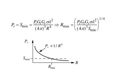
It easy to see that the radar detection range is proportional to σ∧¼ where σ is the radar cross-section (the RCS ,the measure of a target’s ability to reflect radar signals in the direction of the radar receiver, often measured in dBsm or m2). Reducing the cross-sectional area, therefore, affects radar range, although only according to the fourth root. However, by carefully designing an aircraft, the value of σ may be reduced by many hundreds of times thus present an effective approach.
It is important to note that stealth aircraft are not invisible, the goal is to delay enemy detection as much as possible.

Contributors to high RCS:
To start with, the total radar reflection of a complex body such as aircraft made from several different kinds of reflections:
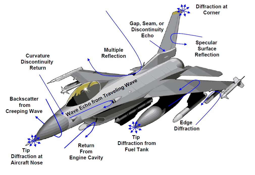
They can be grouped into these following types:
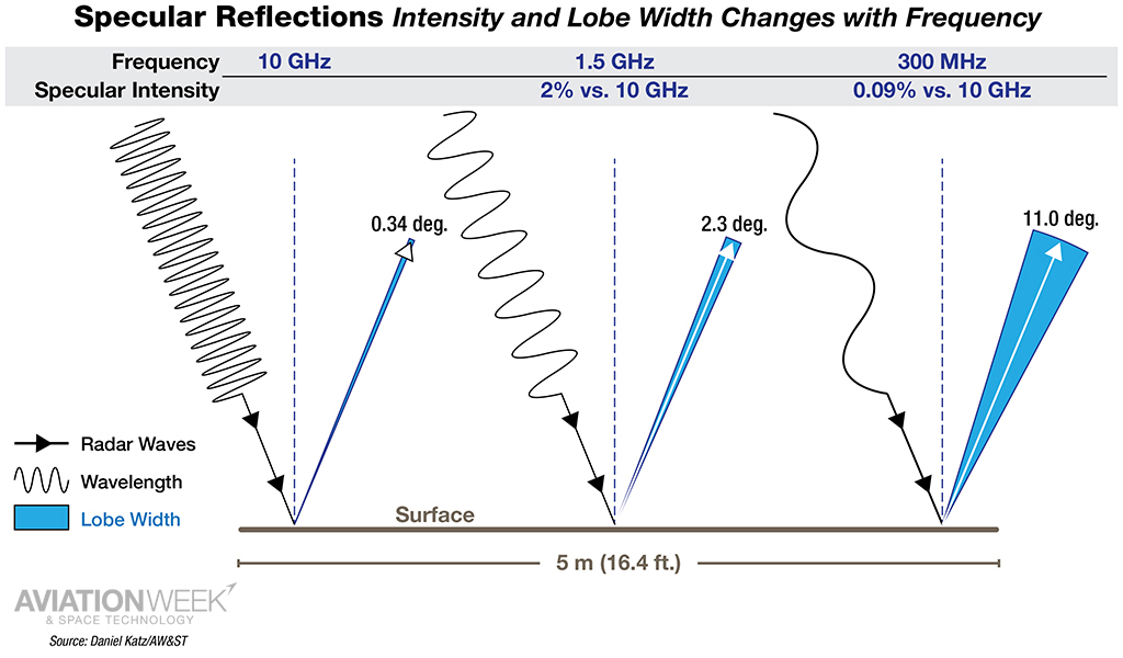
Specular return: this is the most significant form of reflection, the surface acts like a mirror for the incident radar pulse. Most of the incident radar energy is reflected according to the law of specular reflection ( the angle of reflection is equal to the angle of incidence).
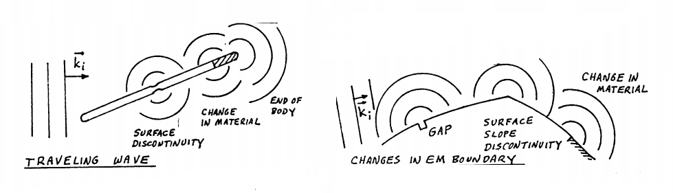
Traveling/Surface wave return: an incident radar wave strike on the aircraft body can generate a traveling current on surface that propagates along a path to surface boundaries such as leading edge, surface discontinuous …etc, such surface boundaries can either cause a backward traveling wave or make the wave scattered in many directions.

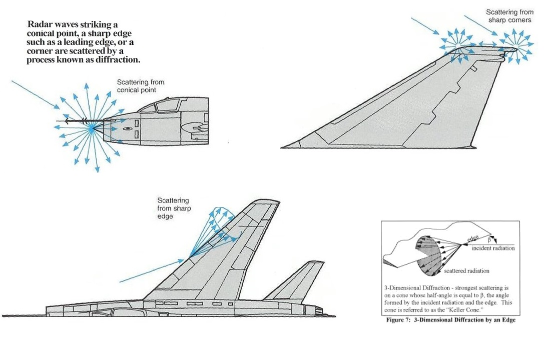
Diffraction: waves striking a very sharp surface,and edges are scattered instead of following the law of specular reflection.
Creeping wave return: this is a form of a traveling wave that doesn’t face surface discontinuous and not reflected by obstacle when traveling along object surface, thus it is able to travel around the object and come back at the radar. Unlike normal traveling wave, creeping wave traveled along surface shadowed from incidence wave (because it has to go around the object). As a result, the amplitude of creeping wave will reduce the further it has to travel because it can’t feed energy from the incident wave in the shadow region. In principle, creeping waves are the result of waves hitting the tangent of a tubular or circular body then get diffracted into the shadow region. It important to note that the creeping wave return effect appears when the wavelength is at least 1/10 of the object’s circumference and the effect is most powerful when wavelength equal to the circumference of the object.


Basic RCS reduction approaches:
1) Shaping
- Orientation and curvature of surfaces
- Alignment of edges
- Shielding of cavities and ducts
2) Materials selection
- Composites and RAM
- Metamaterials and other artificial materials
RCS reduction techniques:
Surface orientation (to deal with specular return):
- Make sure surface normals do not point in high priority threat directions
- Specular component is frequency independent, but scattering lobe widths decrease with increasing frequency
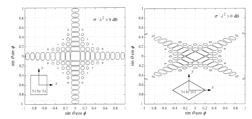
- Principal planes (i.e., cuts with the highest sidelobes) are perpendicular to edges
Example above: square versus diamond with the same surface area
Retro-directive Reflectors (to deal with specular and surface wave return):
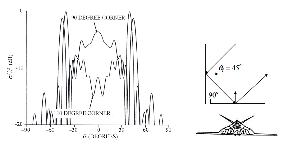
- Avoid corner reflectors (dihedral and trihedral reflectors)
No vertical/horizontal tail surfaces on aircraft - Surface orientation is the most important feature of a stealth aircraft, even without radar absorbing materials, a stealth airframe can achieve much lower RCS compare to conventional aircraft
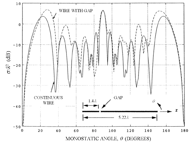
Discontinuities treatment (to deal with traveling-wave return, diffraction, creeping wave return):
Gaps in conductivity lead to edge diffraction. A surface can look continuous, but there may not be good conduction between the two sides. Once traveling waves hit a discontinuity, they diffract in all directions and once traveling wave travel to the end of a surface, it can come back from the other side.
Example 1: RCS Comparision between continuous wire and wire with a break
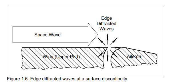
Example 2: gaps between wing and aileron
Solution:
- Minimize the number of edges and gaps on the surface.
- The maximum intensity of the diffracted lobe from an edge (in the Keller cone direction) increases with edge length. Serrations are used on unavoidable gaps and discontinuities to break up edges length to reduce lobe intensities


- Trailing edge and serrated panel are designed so that reflection lobes and creeping wave return lobes point to low priority directions.

- Surface wave absorber is used in panel gaps and trailing edges (notice the distinct color)
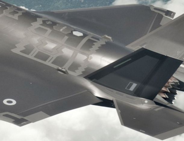
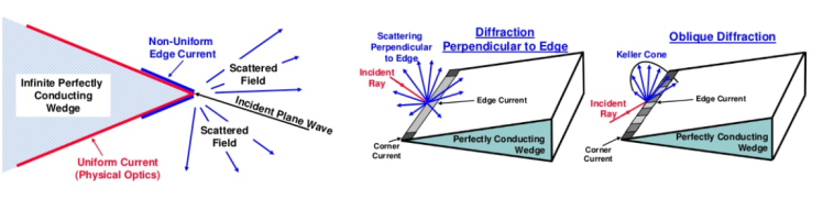
Leading and trailing edges treatment
When radio waves hit a sharp conductive wedge such as the leading edge or inlet lips of aircraft, they scattered strongly in all directions.
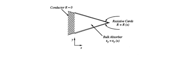
- To reduce this effect, one common method is to make the leading edge of aircraft a soft electromagnetic surface, this is done by stick a high resistive strip on the edge. The strip is designed in such a way that the resistivity will reduce from the maximum electrical resistance at the edge front to near zero at the rear. This allows the surface current to transition slowly rather than abruptly as well as be absorbed. To improve further the edge can be made from radar absorbing material

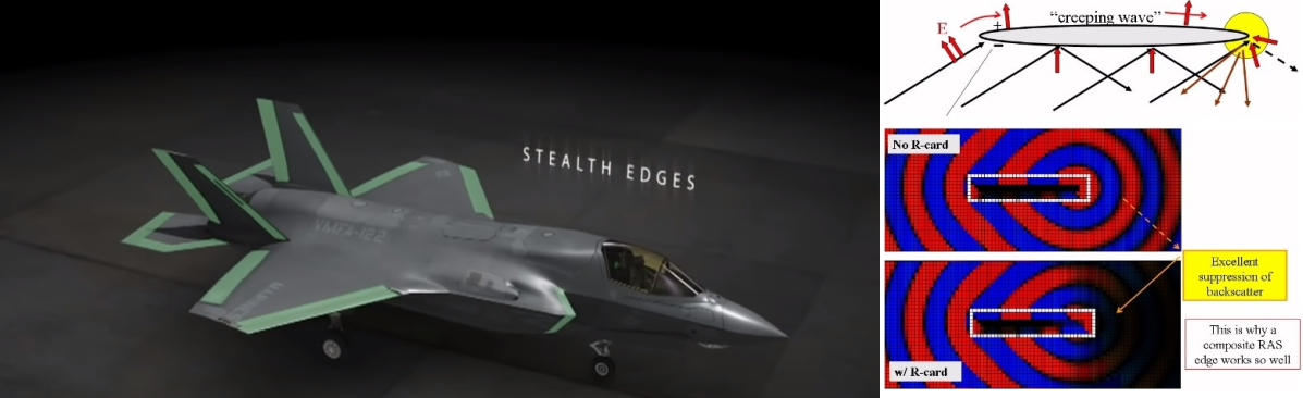
Furthermore, surface wave can travel along surface of aircraft wing and return back from the other side
- A solution for this is to apply a thin resistance strip on the surface of the wing trailing edge to absorb the energy of the surface wave, thus reduce the magnitude of creeping wave return reflection
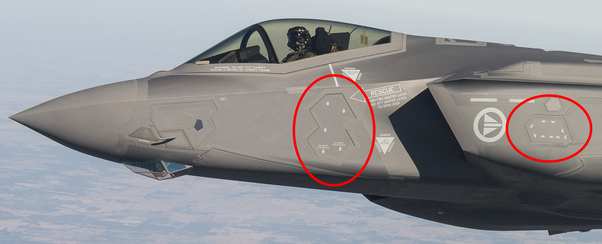
The trailing edge and leading edge treatment is most noticeable by the distinct color in the leading edge and trailing edges of stealth aircraft.

Passive Cancellation:
- Approach: add a secondary scatterer and adjust it so its scattered field cancels that of the bare target
- Only effective over a narrow range of angles and frequency bandwidth
- Only practical for canceling low RCS levels
- Examples: parasitic elements and lumped loads

- Passive cancellation structure ( or RAS )
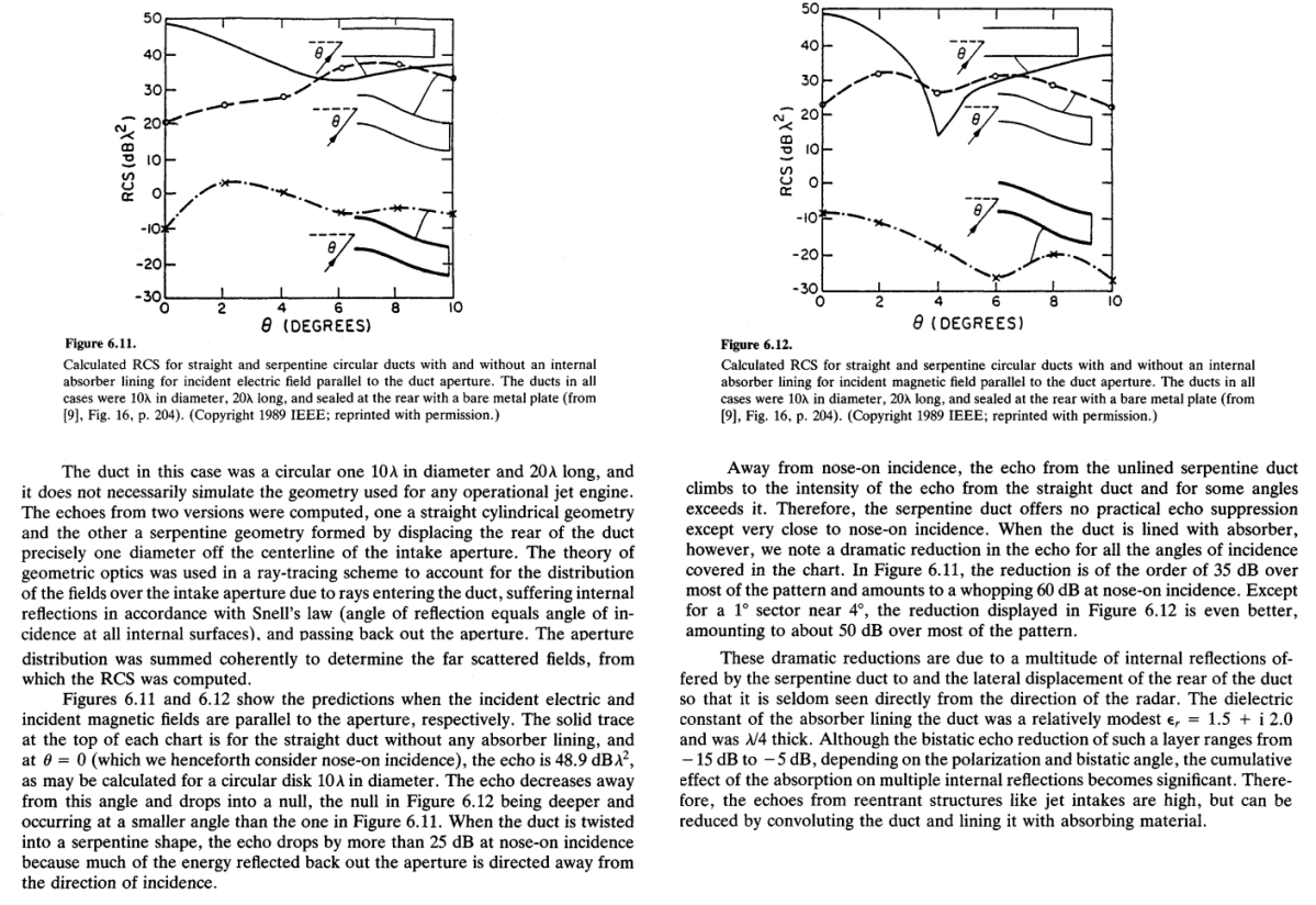
Intake RCS reduction:
- Intake cavity and engine fan blades are a great source of radar reflection. Stealth aircraft intakes are often more sophisticated, for example F-35, F-22, B-2 inlet being a serpentine duct rather than a direct, more conventional intake they use complex techniques to reduce reflection over a range of frequencies. The intake is designed to counter radar threats at three wavelengths loosely termed long ( 30 cm), medium ( 10–20 cm) and short ( 3 cm), equating to 1 GHz (long-range surveillance radar), 1.5–3 GHz (AWACS radar) and 10 GHz (fighter radar) respectively.
- At long wavelengths (30 cm ) the stealth fighter inlet ducts behave as follow:
- At medium wavelengths (10-20 cm ) the stealth fighter inlet ducts behave as follow:

- At medium-short wavelength, stealth fighter inlet ducts behave as follow:
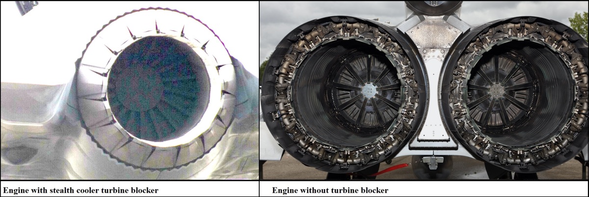
 An alternative way to reduce radar reflection from the inlet cavity and the engine fan blades is by using an engine fan blocker, such solution is being used on F-18E/F, F-117, Su-57 and X-32.
 The main advantage of inlet blocker over serpentine duct is lighter weight. However, the structure of serpentine duct can support thicker layer of radar absorbing material thus giving better absorbing capability. Moreover, serpentine ducts will always make radio wave bounce multiple times inside before reflected back, thus even if the RAM coating of the duct has modest absorbing capability of -5 dB to -15 dB, the total accumulated absorbing power can reach 60 dB
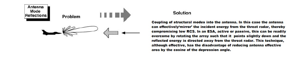
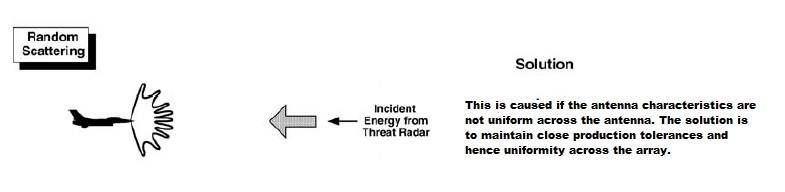
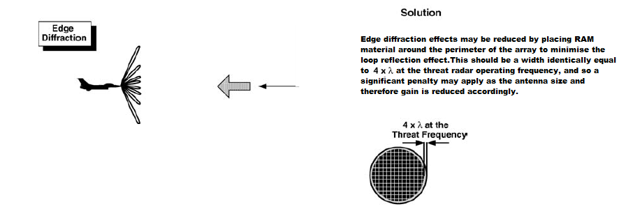
Radome RCS reduction:
- Antenna mode reflections. The antenna mode reflections mimic the antenna main beam and sidelobes.
- Random scattering. This is caused if the antenna characteristics are not uniform across the antenna.
- Radar antenna edge diffraction. Mismatches of impedances at the perimeter of the antenna can cause reflections called edge diffraction. In effect the outer perimeter of the antenna acts as a loop and reflections tend to be abeam of the antenna rather than fore and aft.
Canopy RCS reduction:
- Radar waves can go through the canopy and reflected off objects inside the cockpit, thus increase RCS significantly. Solution: coat the inner of the canopy with a thin layer of gold to prevent radar waves from entering the cockpit, the outer cockpit is coated with transparent radar absorbing materials.
- Example :
Weapons RCS reduction:
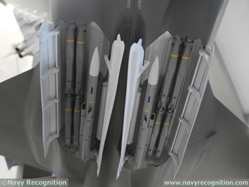
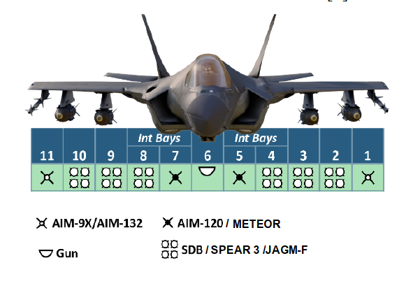
Missiles, bombs are all great contributors to radar reflection due to the perpendicular angle of their wings, fins, Pylons is another great contributors because of the corner they make with aircraft wing. As a result, stealth aircraft often carry weapons internally, the added benefits is the reduction in drag. However, due to the limitation in size when using internal configuration, a stealth fighter cannot carry as many weapons as a normal fighter. In some case, external pylons of stealth aircraft are designed to have a unique shape so as to reduce their signature.
Example: radar scattering characteristic of short range heat seeking missiles
Example: F-35 weapons bay

Example: Low observable pylon vs legacy pylon

Skin RCS reduction:
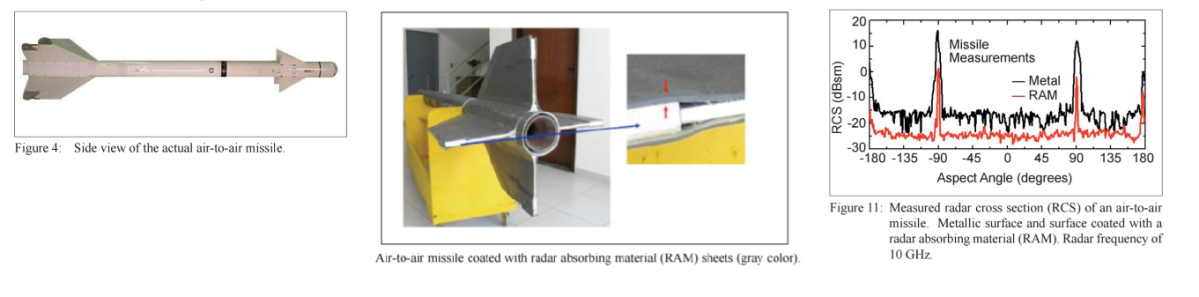
No matter what shape they have, airframe will always reflect radar waves.The only different that shaping will make is the directions that the airframe will reflect radar.While this may be enough in most situation.The adversary may consist of very complex radar network that can illuminate stealth platform from different angles, so along with unique shaping to redirect radar wave from the original source, stealth aircraft often have radar absorbing paint or use radar absorbing material (RAM ).One might be very tempted to construct stealth aircraft skin from such “radio transparent” materials, but radar would then reflect off objects beneath the surface such as sensors, fuel, metallic airframe and engine parts and the pilot.The result may be a RCS value even higher than if the skin was radar reflective. As a result, in practice, the bottom layer of a stealth skin is a highly conductive material, such as metal, which strongly reflects radar waves before they reach the complex reflecting environment below.
Electromagnetic wave consist of two components, the magnetic field and electric field which perpendicular to each other and perpendicular to the direction of travel of the wave

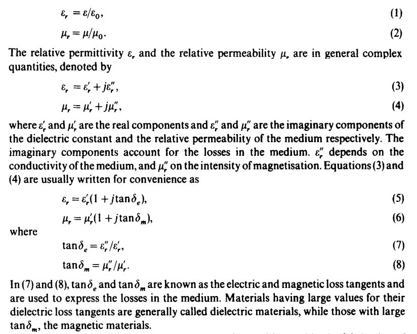
The ability of a substance to absorb electromagnetic (EM) waves depends on two material properties called permittivity (using the symbol ε ) and permeability (using the symbol μ). Permittivity represent the material ability to store electrical energy while permeability represent the material ability to store magnetic energy

The source of both is the existence of electric or magnetic dipoles at the atomic, molecular or crystal lattice level. When an EM wave passes through the material, these dipoles orient opposite to the field’s direction. In some materials, the dipoles effortlessly return to neutral after the EM field returns to zero. In other materials, the dipoles are “sticky” and require energy to orient them or return them to neutral. That additional energy is lost and the material’s permittivity or permeability is said to have a loss component. As its permittivity, permeability (loss components) increase, a material can absorb more EM energy because EM wavelengths shrink as these values rise. Normally the permittivity ε and permeability of a material is compared with the free space permittivity (using the symbol ε0 )and free space permeability (using the symbol μ0) to get the relative permittivity (using the symbol εr) and relative permeability (using the symbol μr ).
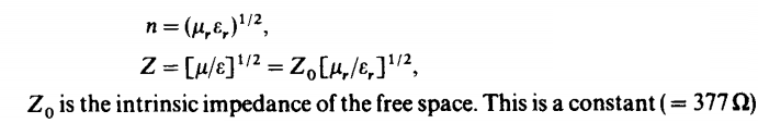
Common sense would let us to believe that calculating the relative permeability and permittivity of material is redundant when the exact value is already known, but that way of thinking is incorrect. The reason is that, for radio wave to be absorbed by the radar absorbing material, it must entered the material first. When waves reach a boundary between two mediums (from free space to material), energy can be reflected rather than admitted. The propagation of radio wave through a material depends on two quality the refractive index n and the characteristic impendence Z .
Whereas the amount of specular reflection and transmission of electromagnetic wave at a boundary is expressed in the form of Reflection coefficient (using the symbol R or Γ) and Transmission coefficient (using the symbol T).
When the electric field polarization is perpendicular to the plane of incident the reflection coefficient at the boundary will be:
 When the electric field polarization is parallel to the plane of incident the reflection coefficient at the boundary will be:
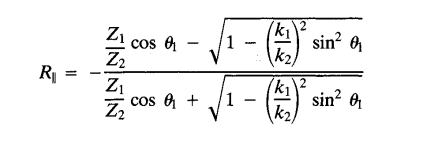
Z as mentioned earlier represent the medium intrinsic impendence (in most case the first medium is the free space while the second medium is the material) and k represent the wave number which is given by:

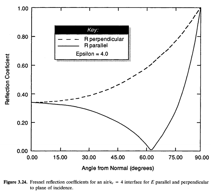
From the equation we can see that reflection coefficient varied with incident angle, medium impendence and polarization, it is important to note that, for parallel polarization, the reflection coefficient will become near 0 at about 65 degrees, this also known as the Brewster angle
When the incident angle is perpendicular to the material boundary, the reflection coefficient of horizontal polarization and vertical polarization will be the same and will equal to:

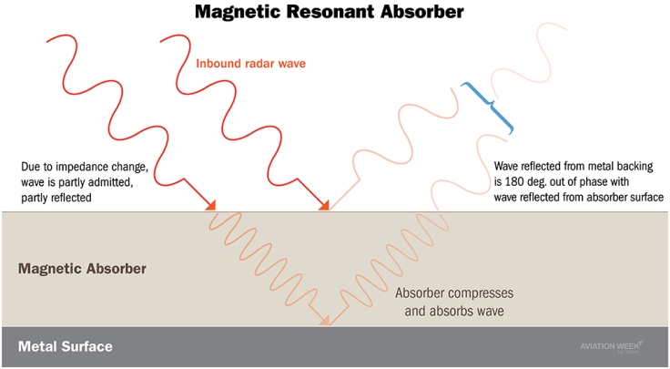
If the second medium is a very good conductor (such as metal) so that the impendence is very low => Z2=0, then R = -1, that mean the wave get reflected entirely and get a 180 degrees phase change. On the other hand, if the second medium has very high impendence then R = +1, that mean all the wave energy still get reflected but without a phase change. However, if the second medium has the same impendence as the first medium Z1 = Z2 then R =0, that mean all the radio wave transmitted from the first medium to the second medium and no energy is reflected. To sum up, the greater the impedance change, the more energy is reflected before it can be absorbed. So RAM design must balance absorptivity with surface reflectivity to maximize absorption. The equation tell us that, if the goal is to get small reflection, the wave should never see a big change in impendence, instead a small gradual change in impendence is desired.
In general, RAMs are composites made up of a matrix material and a filler. The matrix is a low-loss dielectric material with appreciable permittivity and negligible permeability. They are effectively “transparent” to EM waves and are usually chosen for their physical properties. Typically, they are insulating polymers like plastic, glass, resin, polyurethane and rubber. Ceramics have higher permeabilities and heat tolerance. Foams and honeycombs have especially low permittivity—electrical energy storage—because they contain a lot of air. The RAM filler, on the other hand, is typically particles composed of or coated with a lossy material. Carbon is the material of choice for dielectric absorption because electrical lossiness is proportional to conductivity and carbon’s conductivity is below metals but above insulators. Magnetic absorbers, which have some permittivity but far greater permeability—magnetic energy storage—are typically carbonyl iron (a pure powdered form of the metal) or iron oxides, also called ferrites. These materials can be impregnated into rubber or dissolved into a paint and ferrites are often sintered into tiles.
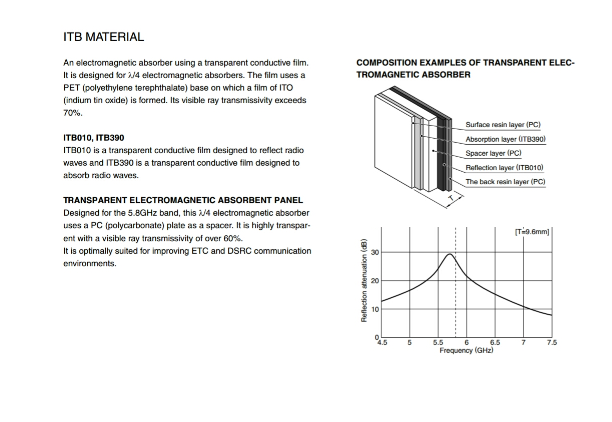
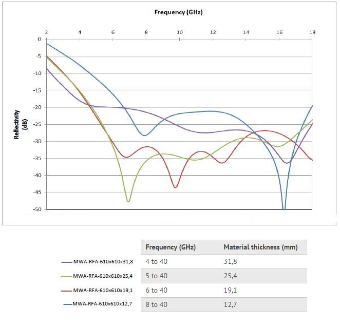
A material’s EM properties also varied significantly with frequency. At higher radar bands, no magnetic materials have permittivity and permeability in a ratio close to that of air, so high surface reflection is inevitable. However, if the material is a quarter-wavelength deep, reflection from the metal backing partially cancels the surface reflection. Radar absorbing materials operate via phase cancellation like this is often called magnetic absorber. Because of the high permeability of magnetic RAM, the depth required is small. Absorption performance of 20 dB (99%) is achieved by commercially available “resonant absorbers” with resonant frequencies of 1-18 GHz and thicknesses of 0.04-0.2 in. The main disadvantages of such absorber is very narrow absorbing bandwidth, however, with significant absorption extending perhaps 15% from the resonance frequency.


Given that magnetic absorbing material has limited bandwidth, as well as high weight and cost, dielectric absorbers are often preferred for wideband absorption at high frequencies. Since dielectrics have no magnetic properties, their impedances never match air, but by using layers of materials—each with an increasing concentration of carbon particles—permittivity, conductivity and dielectric losses all gradually increase while impedance gradually decreases. Layers can also be adjusted to maximize cancellations. These graded dielectric absorbers can reduce reflection by 20 dB, and their bandwidth easily covers higher frequencies. High levels of reflection loss, in many cases better than 20dB, can be achieved in materials which are <1/3 wavelength thick. One of the most common type of graded dielectric absorber is the reticulated foam absorbing material.
Another approach is to use a physical gradient. These “geometric transition” absorbers use pointed objects of homogeneous material oriented perpendicular to waves. At high frequencies, waves bounce among these structures, losing energy with each strike. If the wavelength is large relative to the structure, the waves act as though encountering a gradual change in material properties rather than a geometric shape. Absorbers of this type can reduce reflection by up to 60 dB, but require structures very big structures and high weight so their only application is the pyramidal absorbers that line anechoic chambers used for RCS testing.

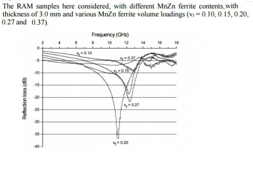
It is a common misconception that radar absorbing material is only effective around X band (8-12 Ghz) or that RAM work at low frequencies will always need to be thick or heavy. In fact, some magnetic materials actually become more effective at lower frequencies because their energy storage (permeability) increases. At frequencies of 30-1,000 MHz, certain ferrites exhibit extreme wave compression and impedance close to air. Commercial ferrite tiles can achieve over 20 dB reduction in VHF band and 10 dB reduction through UHF, with a thickness of only 0.25 in. and a weight of 7 lb./ft.2.
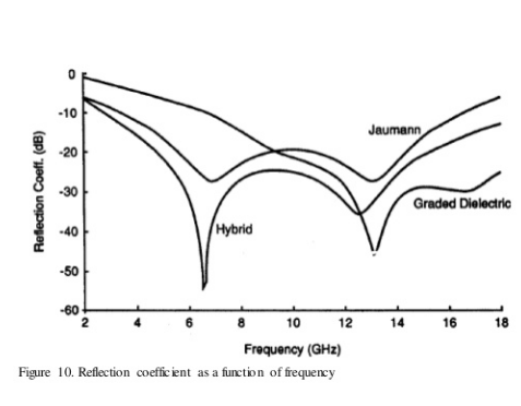
So far, what has been discussed is reducing specular reflections—those that bounce off an object like light off a mirror—but RAM is also particularly effective at reducing surface waves. These are the waves emitted by currents induced in a conductive surface when struck by radar. As they move along the surface they emit traveling waves, usually at angles close to grazing, and when they encounter discontinuities—an airframe edge, a gap or step in the surface or a change in material—they emit edge waves, concentrated closer to the specular reflection. Surface currents travel along a material’s length rather than through its thickness, and the RAM acts as a waveguide, trapping the currents and absorbing them. Magnetic RAM can suppress surface currents well in a thickness of only 0.03 in. There are ways to combine techniques. Layered magnetic materials can reduce RCS by 10 dB from 2-20 GHz with 0.3 in. of depth. Hybrid RAMs can be created with a front layer of graded dielectric and a back layer of magnetic material to attenuate radar reflections from VHF to Ku-band (30 MHz-18 Ghz).
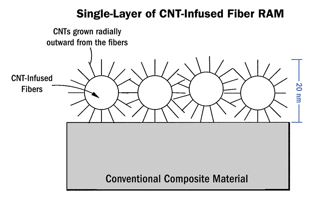
One disadvantage that all radar absorbing materials mentioned above share is that they add weight and volume without adding structural integrity. The radar absorbing materials developed for F-117, B-2 F-22 can kept their RCS small, but their maintenance burdens proved too heavy. Their durability disappointed, necessitating frequent replacements that ballooned support costs and time while restricting aircraft availability. RAM fillers tend to be spherical, a few to tens of micrometers in size and densely packed, which is good for absorptive qualities but bad for durability. Bonding them to aircraft surfaces also proved troublesome. As a result, from the beginning of the F-35 program, Lockheed’s goal was to achieve acceptable stealth while reducing maintenance needs. In May of 2010, Tom Burbage, then executive vice president for the F-35 program, disclosed the incorporation of “fiber mat” technology, describing it as the biggest technical breakthrough they’ve had on F-35 program. The fiber mat would replace many RAM appliques by being cured into the composite skin, making it durable. Burbage further specified the mat featured a “non-directional weave” which would ensure EM properties do not vary with angle. Baked into the skin, this layer could vary in thickness as necessary. Lockheed declined to provide further details, citing classification. Without further evidence, fiber mat would imply the use of fibers, rather than particles, which would make for stronger surfaces and the word “conductive” points to carbon-based RAM. That wasn’t the first time it is hinted that F-35 has a unique kind of RAM. One month before Burbage’s disclosure, Lockheed filed a patent claiming the first method of producing a durable RAM panel. The patent details a method for growing carbon nanotubes (CNT) on any kind of fiber—glass, carbon, ceramic or metal with unprecedented precision in control of length, density, a number of walls, connectivity, and even orientation. The CNT-infused fibers can absorb or reflect radar, and connectivity among the CNTs provides pathways for induced currents. Moreover, the CNTs can be impregnated with iron or ferrite nanoparticles. Fibers can have differing CNT densities along their lengths and homogenous fibers can be layered or mixed. The embodiments described include front layers with impedance matching air, use of quarter-wavelength depths for cancellation, stepped or continuous CNT-density gradients and continuously varying densities at specific depths for broadband absorption. The fibers can be disposed with “random orientation” in materials including “a woven fabric, a non-woven fiber mat and a fiber ply.”.The patent claims composites with CNT-infused fibers are capable of absorbing EM waves from 0.1 MHz to 60 GHz with particular effectiveness in L- through K-band.That is a bandwidth unheard of commercial radar absorbing material before. The patent does not quantify the absorptivity, but does say the panels would be “nearly a black body across . . . various radar bands.” Also, interestingly, a layer can be composed so an attached computer can read the induced currents in the fibers, making the layer a radar receiver.While the patent mentions stealth aircraft, it does not mention the F-35 specifically, and the manufacturing readiness level of the material at the time it was granted is not known. But the proximity in timing and technology of the filing to the “fiber mat” disclosure is hard to ignore.
Results:
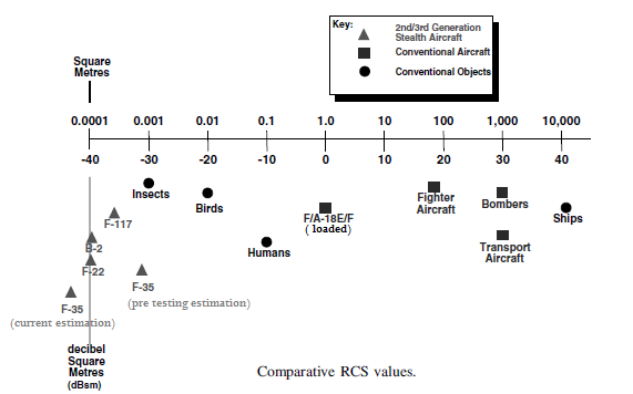
With careful designs stealth aircraft can have RCS equal a fraction of conventional aircraft.
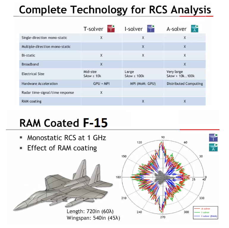
Radar scattering chart of stealth F-35 and some conventional aircraft
Example 1: Simulated radar scattering chart of F-35

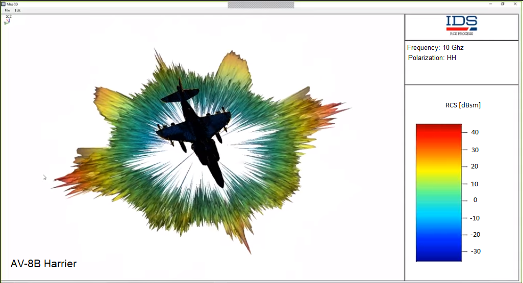
Example 2: Simulated radar scattering characteristic of AV-8B Harrier (conventional aircraft)
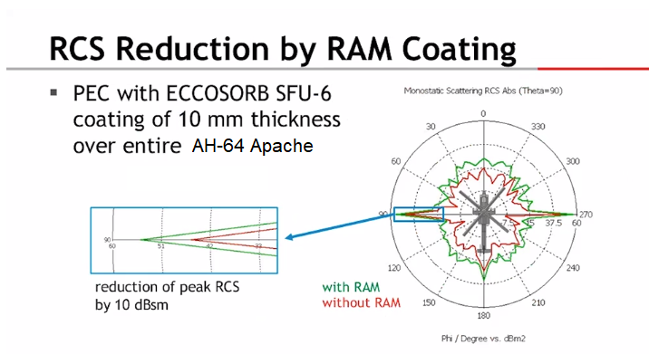
Example 3: Simulated radar scattering characteristic of AH-64 Apache
Example 4 Simulated radar scattering characteristic of F-15 at 1 Ghz
Example 5: radar scattering chart of Mig-21
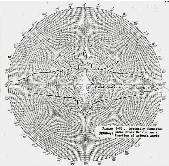
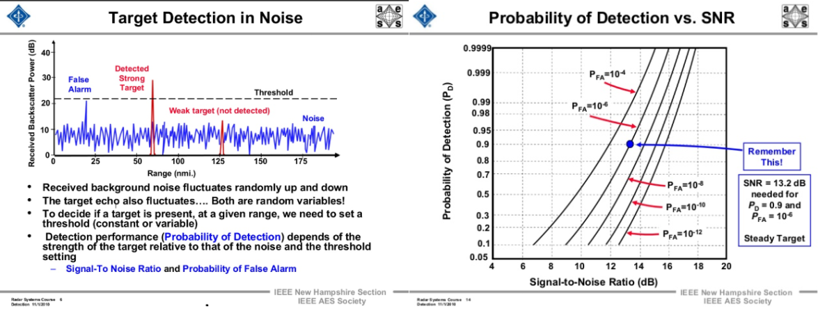
When looking at radar scattering graph of aircraft, one common mistake is to assume that aircraft will be detected by radar at a significantly longer distance from the side aspects or tail aspects, because radar scattering charts often show much higher radar cross section values for beam aspect and tail aspect compared to the frontal aspect of aircraft. That misconception raised from the fact that most enthusiasts treat radar return as equally valuable regardless of aspect angle. That is not the case, however, and here is why:
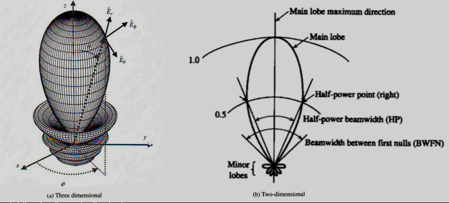
Most radar energy is transmitted and received via a main lobe aligned with the antenna’s boresight, but smaller amounts enter through sidelobes that point in almost all directions.
Radar performance degrades at viewing angles where a target must be distinguished from background clutter. Clutter can enter the receiver via the sidelobes, and the processor has no way of knowing the return did not come from the main lobe. Such returns can mask that of the target. Modern radars mitigate this phenomenon with Doppler processing. A pulse-Doppler radar records the time of arrival of a return and also compares its phase with that of the transmitted wave. The difference between the two reveals the target’s radial velocity. The computer creates a 2D range/velocity matrix of all returns, which puts approaching targets in cells with no stationary ground clutter. This is why airborne radars exhibit their best detection ranges against approaching targets. But if the target is being chased, its radial velocity will match some of the ground clutter, and it will be harder to detect.

For example, the Sukhoi Su-35’s Irbis-E radar in high-power, narrow-beam search can detect a 3-m2 (32-ft.2) target at 400 km (250 mi.) from the front but only 150 km from behind, and these ranges drop by half in normal search mode. The hardest airborne targets to see are those moving perpendicular to the radar, because their Doppler profile matches the ground directly below the aircraft. For ground-based radars, the same principles apply, but the antenna is stationary. Fleeing targets stand out as much as approaching aircraft. But ground-based radars are especially challenged in detecting targets moving perpendicularly, because their Doppler profile matches the stationary clutter all around. A tactic used by fighter pilots against ground radars, called “notching,” is to turn perpendicular to the radar, placing the aircraft in the “Doppler notch” in which the radar suffers significantly reduced range.
Benefit of low RCS
- Reduce radar detection range:
One easy to see benefit of RCS reduction is the deduce in enemy detection range ,thus giving pilots more times to react to the threat or getting into weapon engagement zone
Example : radar detection range between conventional and stealth aircraft.
- Improve jamming effectiveness:
It is a common misconception that stealth technology is short live and as radar get more powerful, soon, they will be able to out range weapon engagement envelop , thus renders all money spend on RCS reduction a waste. This impression is inaccurate because any technology that can increase a radar peak power or gain will also benefit a jammers in the same ways. And stealth has a synergy relationship with jamming .
Another common opinion is that the gap in RCS can easily be close by using a more powerful jammer .This is also inaccurate because RCS directly proportional to the power required to jam a radar at a certain distance.Which mean when RCS is reduced to 1/100th the original value, the required jamming power is also reduced to 1/100th the original value to achieve the same effect.In others words, if a stealth aircraft need a 10 kW jammer , a conventional asset will need jammer with power of 10Mw or more
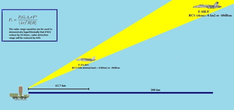
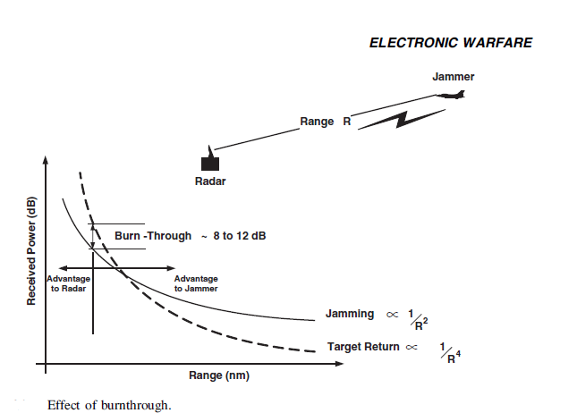
If the jamming power is keeping the same then burn-through range is reduced by 10 times, which mean stealth assets( RCS =0.001m2 ) can get 10 times closer the threat compared to conventional aircraft ( RCS=0.1m2).In other words ,even if adversary radar can see through jamming of conventional assets from 400 km aways, a stealth asset can still get within 40 km of such radar using exactly same jamming system
- Example : burn-through distance of F-35 compared to Rafale with same jamming assets, same threat radar ( image not to scale )

- Burn-through Range is the radar to target range where the target return signal can first be distinguished from the Jamming signal ( rendering jamming ineffective).
Low Observability In Infrared Spectrum.
All objects with a temperature above absolute zero emit heat energy in the form of radiation. Usually this radiation is invisible to the human eye because it radiates at infrared wavelengths, but it can be detected by electronic devices designed for such a purpose , these devices are called infrared (IR )sensor. With the improvement in optics and processing power of CPU , nowadays infrared sensors can see much further than human eyes .As a result, all stealth aircraft use one way or another to suppress their infrared signature.
Infrared signature suppression has two objectives:
- Reduce the range at which an IR missile or sensor can detect and track the
aircraft. - Increase the effectiveness of countermeasure systems and devices.
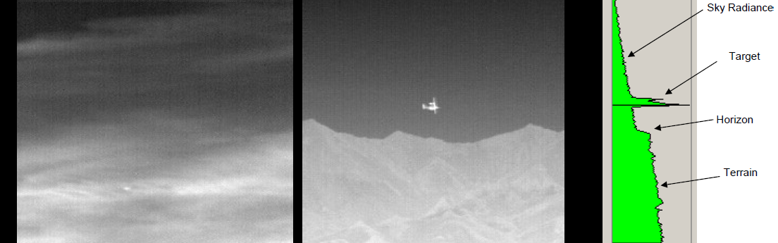
It is important to note that infrared sensor detecting assets by comparing the contrast of such assets infrared signature with background radiation , thus the effectiveness of infrared suppression is affected significantly by the temperature of background. In general clear sky is the worst background due to their low temperature while cloud and/or hot land surface make the best backgrounds for stealth aircraft to hide from adversary infrared sensor.( for the same reason, aircraft fly higher are much easier to detect by IRST )
Example: infrared photo of C-130 in 2 different background
Like all electromagnetic radiation, IR interacts with matter in a variety of ways:
- Reflects—A wave is reflected from a surface. The angle of reflection equals the
angle of incidence. - Refracts—The direction of a wave bends when passing between two transparent
media with different propagation speeds (Snell’s law). - Scatters—Scattering occurs upon interaction with particles whose size
approaches the length of the wave (why the sky is blue). - Diffracts—This interaction occurs around the edges of an obstruction.
- Interferes–This interaction occurs in both a constructive and destructive manner.
- Absorbs—When absorbed by matter, radiation is converted into another form of
energy. The most common conversion is to heat. - Emits—Radiation is emitted from matter by conversion from another form of
energy. - Transmits—IR propagates through a transparent medium (or vacuum).
- Polarizes—An electric field is partially polarized by reflection from dielectric
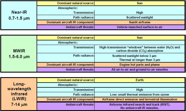
Infrared wavelength range from 0.7-14 µm , divided to short ( 0.7-1.5 µm ) medium (1.5-6 µm ) and long infrared wave (7-14 µm ), with different characteristics they all have different military application.
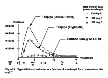
Infrared signature of aircraft:
An aircraft’s infrared signature is a complex mixture of emissions and reflections from different materials with different emissivity and different areas. Signature is complex in its spectral distribution, in its contrast against background, and in its dependence on conditions. Aspect angle, altitude, airspeed, ambient air temperature, power setting, and
sun angle are only a partial list of conditions affecting signature values.
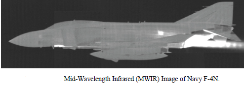
High infrared signature component of fighter aircraft:
- Engine “hot parts,” which usually consist of the aft turbine face, engine center
body, and interior nozzle sidewalls. - Engine exhaust plumes, which are emissions from the combustion constituents
of CO2 and water vapor. - Airframe, which includes all of the external surfaces of the wings, fuselage,
canopy, etc. Airframe signature includes solar and terrestrial reflections, Mach shock wave in addition to direct emissions.
Similar to radar cross section, IR signature of an aircraft is very aspect angle dependence thus lead to very different detection range, For example : OLS-35 ( IRST system on Su-35 ) can easily detect an aircraft from 90 km aways from tail aspect, however in head on aspect the detection range reduce significantly down to 30 km


Airframe Aerodynamic Heating:
The temperature of the airframe is warmer than ambient by the amount of aerodynamic heating. A good estimate of airframe temperature is given by the formula for the recovery temperature given below. Note that the temperature units are Kelvin.The temperature of the skin of an aircraft stabilizes at the ambient air temperature plus aerodynamic heating. Aero heating increases as the square of Mach number. The formula below gives a good approximation:
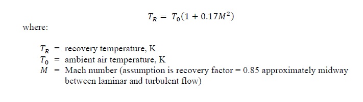
Aircraft moving at supersonic speed also produces compressed air ( Mach cone ) which not only increase the airframe temperature significantly but also increase frontal area present to the infrared sensor.

Aircraft moving at Mach 1 can be detected by IR sensor at twice the distance compare to aircraft moving at Mach 0.8
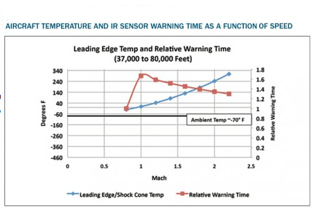
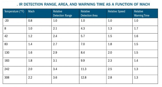
- As shown in table above flying supersonic can increase aircraft infrared signature significantly, so the most simple solution is to stay subsonic, the trade off of such decision is smaller weapon engagement envelope, longer reaction time for adversary , this solution works well in design that high speed is not a requirement such as F-117 , B-2 .
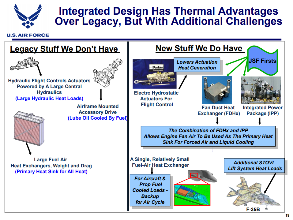
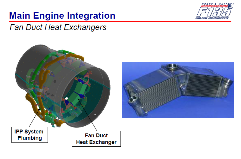
- Another solution is to use fuel as heat sink , most modern stealth aircraft have internal fuel tanks distributed evenly through out the airframe, the fuel being use all the time thus they can transfer the built up heat away from the aircraft. Fuel can also be used to reduce heat generated by electronic equipment, avionics systems like radar and jammer can generate very high amount of heat. Example : fuel tank contribution of conventional aircraft ( on the left) vs stealth aircraft ( on the right)

- Modern stealth aircraft such as F-22 and F-35 are coated with IR-suppressive skin coatings, the exact composition of the coatings is unknow but in general, they have very low emissivity. Emissivity is of the surface of a material is its effectiveness in emitting energy as infrared radiation, coating with a lower emissivity mean the aircraft emit a lower level of IR radiation at any given temperature.
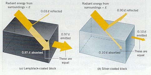
- For example it is reported that the Top coat on F-22 , F-35 can reduce their skin infrared signature in long and infrared wavelength (8–12 microns) by more than half.
- Example of IR suppression coating with low emissivity

- Some type of IR suppression coating also has the ability to shift the the infrared radiation to non-atmostpheric window region, making the IR radiation of aircraft better absorbed by the atmosphere. The main advantage of this IR surpression coating is that it can help lower the inner temperature of the coated object, since the broad-band coating acts as a thermal insulator, the temperature of the underlying object is increased to a much greater extent.
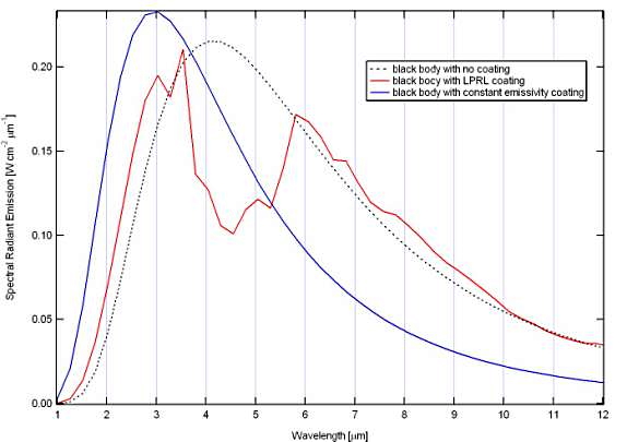
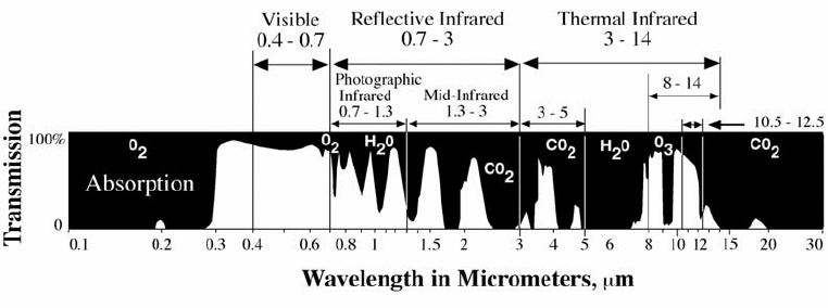
Atmospheric window:
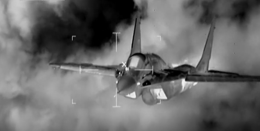
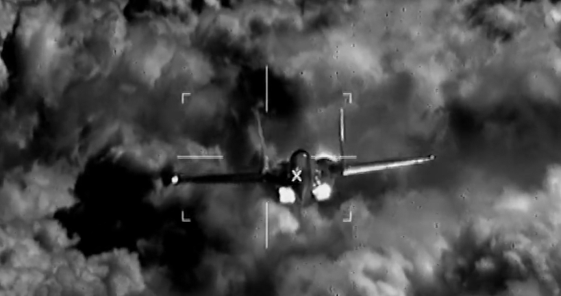
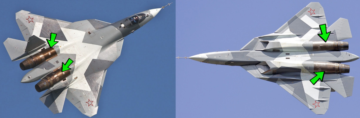
Heating of engine fan blades:
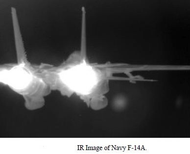
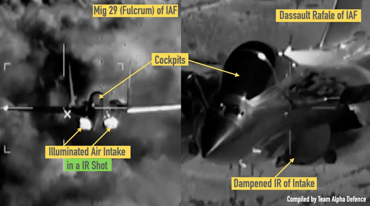
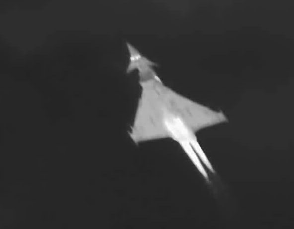
Because all jet engines have very significant rotational speed, even the first stage of jet engine will be heated up to temperature much higher than the airframe skin temperature. As can be seen from photos below, when aircraft use a straight inlet such as on Mig-29/35, Mig-35, Su-27/30/35, F-15, F-14 or exposed nacelle such as on B-52, C-17 the amplitude of infrared radiation from engine fan stage is significantly higher than from fuselage.
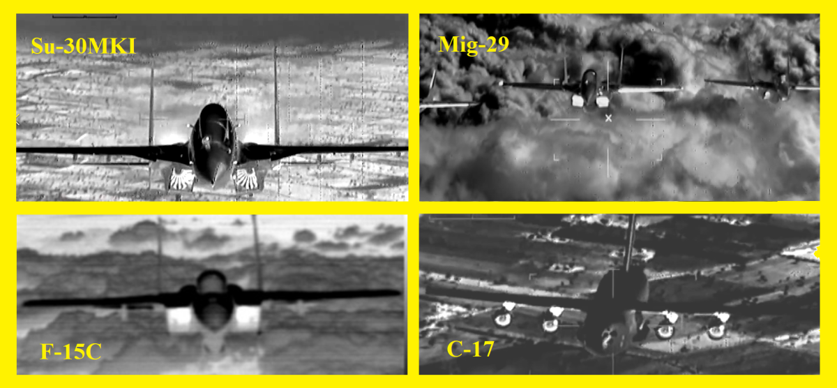
The simple solution to this issue is to either use an S-duct inlet such as on F-35, F-22, Rafale or a physical blocker such as on F-18E/F to block the direct line of sight to the engine fan stage. As can be seen from the photo below, the head on infrared signature is significantly lower on fighter with an S-duct
Internal Equipment Heating:
Electronics equipment such as radars and jammers generate significant amount of heat, the more sophisticated and powerful the equipment is the more heat they will create , cooling are required not only to reduce enemy’s infrared sensor detection range but also to prevent the equipment from being overheat and shutdown
aircraft that lack significant cooling features for electronics often have higher body temperature , thus easier to detect. Lacking cooling also limit the output of their equipment such as radar
For example:
picture of F-16 in mid-infrared wavelength

- Solution : As mentioned earlier , avionics can be cooled using fuels , furthermore aircraft can use open vents, thus atmosphere air can act as heat exchanger with the fuel which got heated by avionics
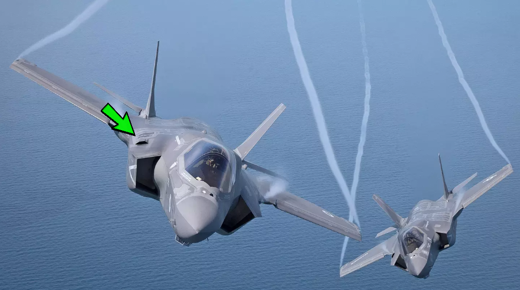
For example: F-35 has a scoop located on the top of the right wing-glove to provide air to the fuel/air heat exchanger. A deployable scoop is located on the left-aft fuselage to provide air to the IPP and to the avionics
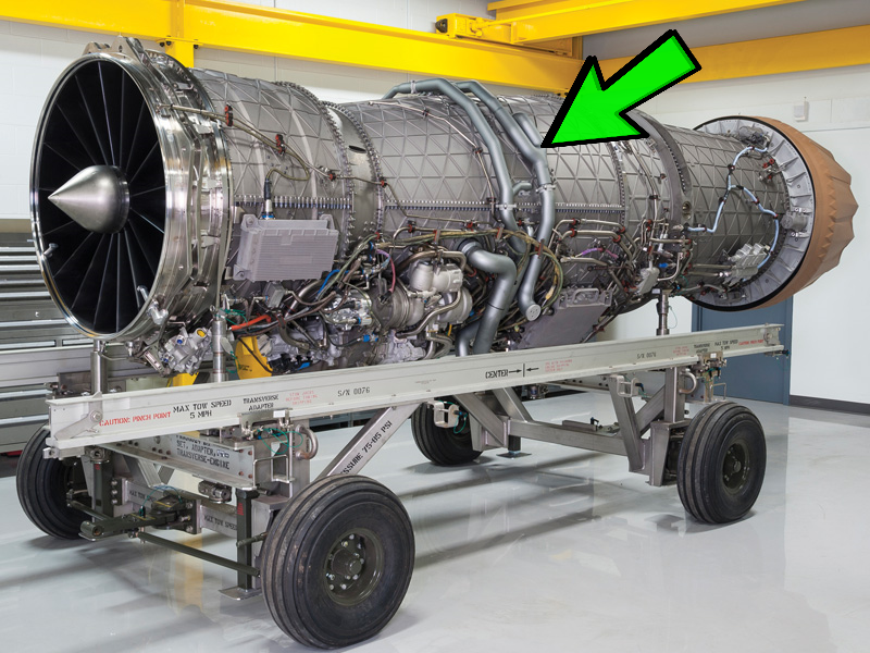
Some stealth fighter also use engines bypass air as heat exchanger
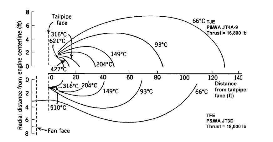
Airframe heating due to engines:
With the core temperature of several hundreds degrees of modern jet engines , without appropriate measuares, they can increase aircraft body temperature dramatically
For example : picture of Typhoon in mid-infrared wavelength
Solution :
- Airframe heating due to jet engines can be reduced by extensive use of cooling vents, the cold air at high altitude provides an isolation layer between the engine and the airframe
For example: the F-35 has two scoops located in the wing/fuselage to provide nacelle bay ventilation


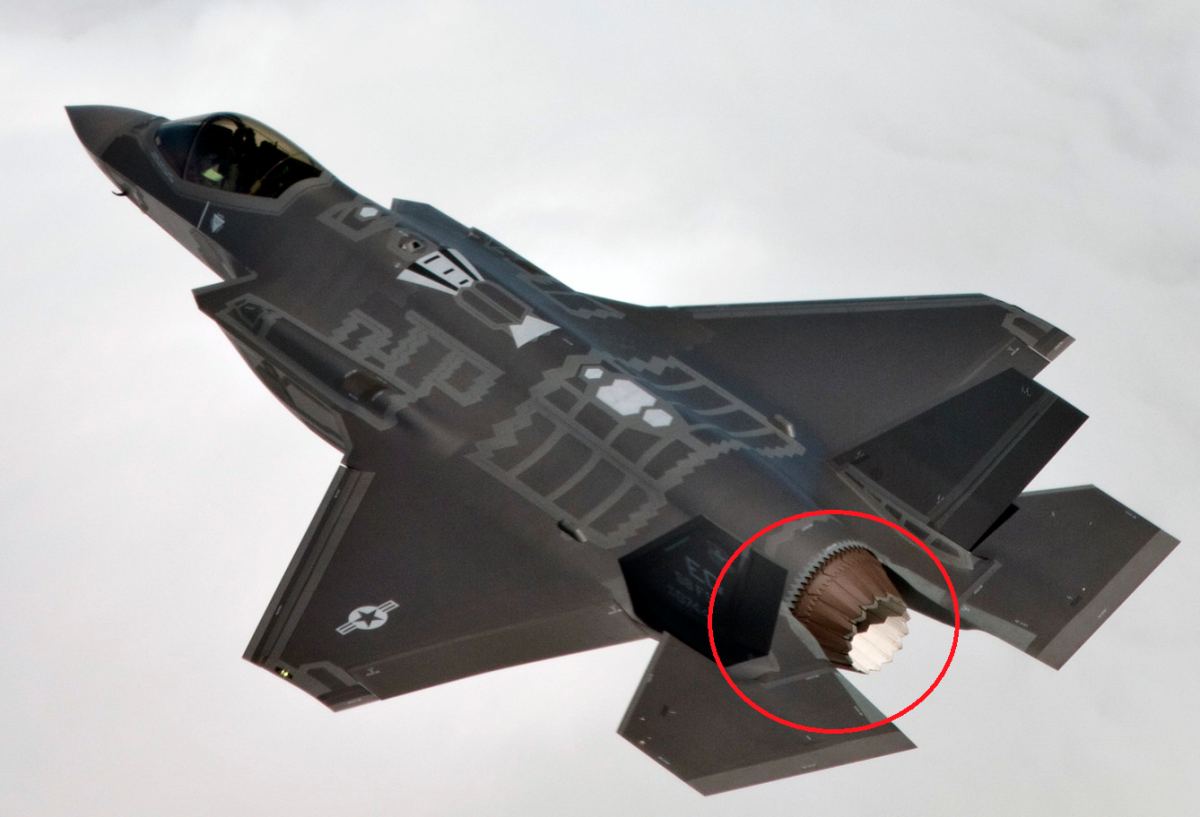
- Moreover, the view to the high pressure turbine stage can be blocked by cooled blocker, thus further reduce the Infrared signature from the rear
Fun fact:
For some fighter aircraft, as their operating envelope include very high-speed flight (above Mach 2) so their engine nacelle can be heated up quickly to very high temperature. Thus, to prevent structure failure, their engine bay is made from titanium which has much higher melting temperature than aluminum. However, most paints have bad adhesion with titanium, especially in high-temperature condition. Furthermore, titanium resists corrosion very well, so no corrosion protection, primer, and paint is required. Thus, on some fighters, the engines area are often left bare without paint and instead what we often see is a silver looking area.


Temperature from the exhaust fumes:
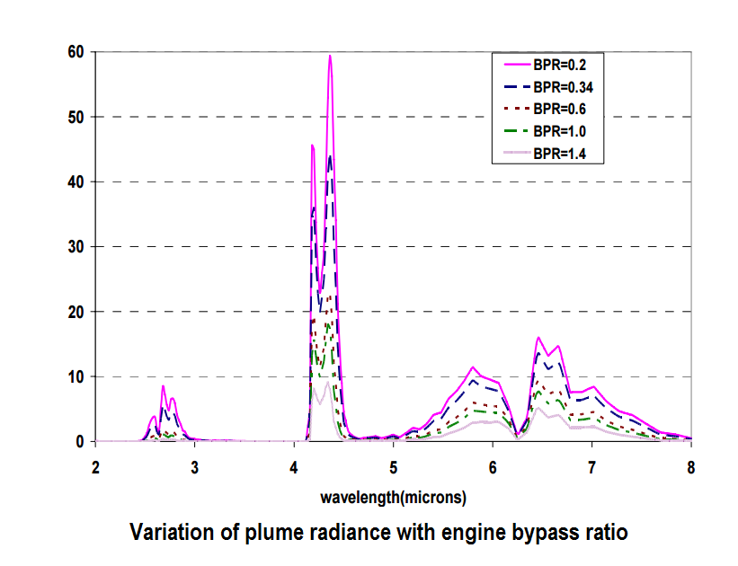
The biggest contributors of signature in mid-infrared wavelength on a jet aircraft is their exhaust fumes, reduction of exhaust temperature as little as 100 degrees can reduce aircraft infrared emission by more than haft
One very common misconception about jet engine and infrared signature is : an engine with higher thrust will always have a higher infrared signature, however that is an inaccurate assumption. It is entirely possible to have higher IR signature with lower thrust value.
To understand why lets have a look at the design of jet engines: below is a diagram of a normal turbofan engine commonly used in all aircraft flying nowadays:
The 2 main components that responsible for thrust are the Fan and engine core.
The compressor , turbine and combustor ( also know as the engine core ) move air at very high speed hence, they are less dependence on air density and aircraft velocity. On the other hand, the fan stage moves air at much slower rate ,which is much more fuel efficient and also mix the exhaust plume with cold air, thus reduce the temperature of the plume. Not all air suck in by the first stage fan will go through the engine’s core (compressor , turbine and combustor ) some will pass through the outer duct. The air that passed through the outer duct is called bypass air. To get to a certain thrust level, an engine can either have very big fan and small core ( good for combat radius and thermal signature ) or very big core and relatively small fan (good for speed and high altitude performance )
- Due to reasons stated above one of the solution for exhaust temperature reduction is to use engines with higher bypass ratio , the trade off of such design choice is the aircraft will not be able to fly very high or very fast. ( For example F-135 have much higher bypass ratio compared to F-119 , EJ200 , Snecma M88 , R-15 ,F404 )
- A common misconception is that engine turbine inlet temperature is also proportional to exhaust temperature, that is wrong, however, in reality, turbine inlet temperature does not reflect the engine case temperature or even the exhaust plume temperature. It simply means that the gasses entering the turbine is at a higher energy state and the engine will yield more gross energy per drop of fuel or air entering the combustor(s). That energy however, is extracted to do work first by the high-pressure turbine, then by the low-pressure turbine before going out the tail pipe at a given velocity. The final temperature depends on how much energy is extracted to drive the compressors and the fan, and how much bypass air is mixed into the exhaust. The F-35 has twice as many low pressure turbine stages which in theory will extract more energy. It also has a bigger and higher pressure ratio fan which adds energy to the exhaust as well as introduce relatively cold air into the mix. The exhaust plume temperature and engine case temperature can never be derived from the turbine inlet temperature alone.
- It is also important to remember that unlike a rocket, jet engines are air-breathing engine, which means their performance depending a lot on air density, the thinner the air the less thrust they will be able to generate, so aircraft thrust will reduce as they go higher. For example: a jet engine that can generate more than 190kN at sea level can be struggled to push out 10kN at 40-50K feet. On the other hand, a rocket engine can generate the same amount of thrust regardless of altitude
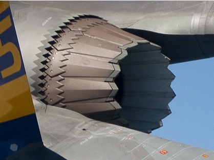
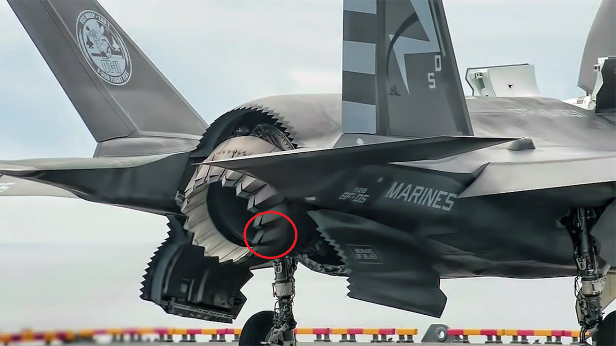
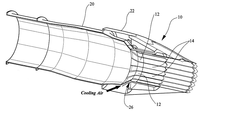
Using high bypass engine is not the only method of reducing exhaust temperature, however. Modern stealth aircraft also use exotic engines nozzles that either long and flat or with the serrated pattern so that exhaust fumes become unstable and mixed quicker with cool ambient air .As a result, the heat will be dissipated rapidly. In some aircraft, there are spacing between nozzle plates linked to cooling vents to help reduce the temperature of outer nozzle surface
Example :
- F-117 and B-2 have flat exhaust nozzles


2.F-35 with serrated nozzle and cooling vents on nozzles

3. Thermal image of exhaust fumes. First nozzle uses conventional circular design. Second nozzle uses serrated design. It is estimated that fumes length is reduced by around 40%

4. Test data comparison between a conventional exhaust nozzle and a serrated nozzle:

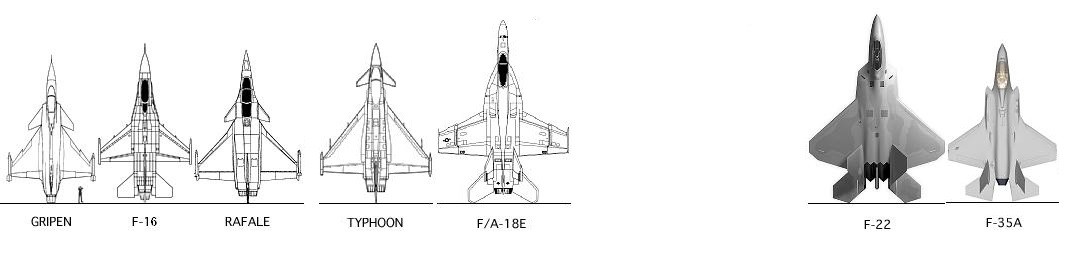
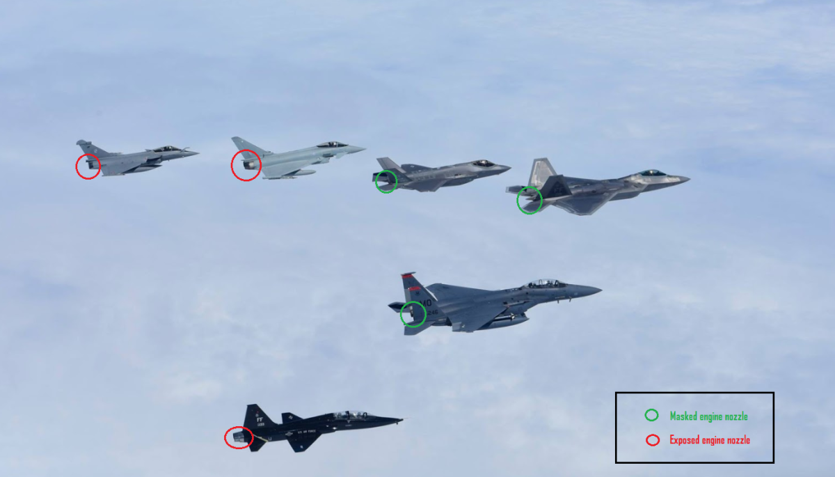
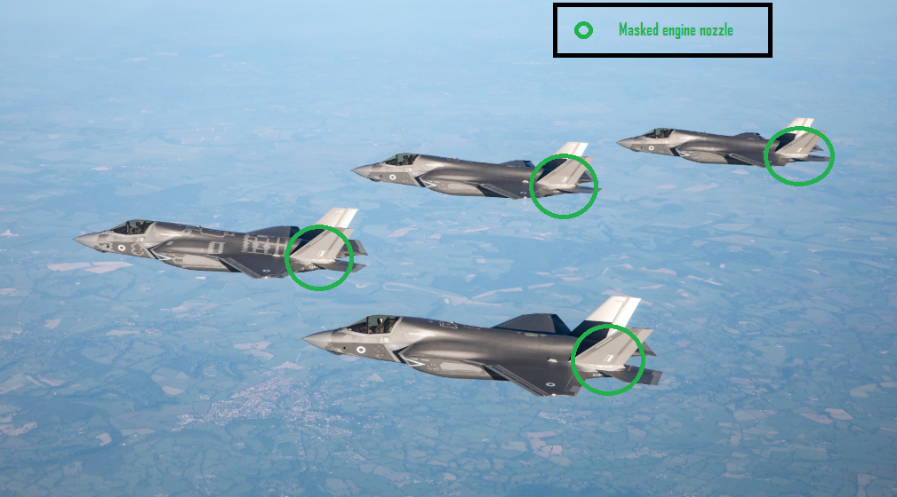
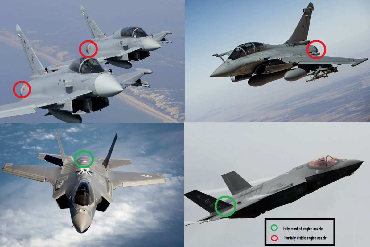
- Stealth aircraft are also designed so that from frontal, the view of their engines nozzles will be blocked by their vertical and horizontal stabilizer
Example: Aircraft ( on the left ) have exposed engine nozzles while aircraft ( on the right ) have masked nozzles
References :
- Barr, E. S. “Historical Survey of the Early Development of the Infrared Spectral
Region,” American Journal of Physics, Vol. 28, No. 1 (January 1960), p. 49. - Herschel, W. “Experiments on the Refrangibility of the Invisible Rays of the Sun,”Philosophical Transactions of the Royal Society of London, Vol. 90 (1800),
pp. 284–292. - Herschel, W. “Investigation of the Powers of the Prismatic Colours to Heat andIlluminate Objects; With Remarks, That Prove the Different Refrangibility ofRadiant Heat. To Which Is Added, an Inquiry Into the Method of Viewing the SunAdvantageously, With Telescopes of Large Apertures and High Magnifying
Powers,” Philosophical Transactions of the Royal Society of London, Vol. 90 (1800),pp. 255–283. - Hudson, R. Infrared System Engineering. Hoboken, New Jersey, John Wiley & Sons,1969.
- Huygens, C. Treatise on Light. London, Macmillan and Co., Limited, 1690.
- Naval Surface Warfare Center. Genesis of Infrared Decoy Flares. The Early Years from 1950 into the 1970s, by B. Douda. Crane, Indiana, NSWC, 26 January 2009.
(ADA495417, UNCLASSIFIED.) - Newton, I. Opticks: or a Treatise of the Reflections, Refractions, Inflections & Colours of Light. The Second Edition, With Additions. Printed for W. and J. Innys, printers to the Royal Society, at the Prince’s- Arms in St. Paul’s Church-Yard, London,
1718. - Planck, M., and Willis, A. P. Eight Lectures on Theoretical Physics. Mineola, NewYork, Dover Publications Inc., 1998. P. 92.
- Sylvania Electronic Defense Laboratories. Radiometry, by F. Nicodemus. Mountain
View, California, Sylvania Electronic Defense Laboratories, 15 March 1965.(Report Number EDL-G324, publication UNCLASSIFIED.) - Westrum, R. Sidewinder: Creative Missile Development at China Lake. Annapolis, Maryland, Naval Institute Press, 1999.
- Schleher, C.D. (1978) MTI Radar, Artech House.
- Schleher, C.D. (1999) Electronic Warfare in the Information Age, Artech House.
- Skolnik, M.I. (1980) Introduction to Radar Systems, McGraw-Hill.
- Stimson, G.W. (1998). Introduction to Airborne Radar, 2nd edn, SciTech Publishing Inc.
- Thornborough, A.M. and Mormillo, F.B. (2002) Iron Hand – Smashing the Enemy’s Air Defences, Patrick Stephens.Joint Advanced Strike Technology Program, Avionics architecture definition – issues/decisions/rationale document, version 1, 8 August 1994. A. Doucet, N. Gordon, and V. Krishnamurthy. Particle lters for state
- Joint Advanced Strike Technology Program, Avionics architecture definition – issues/decisions/rationale document, version 1, 8 August 1994.
A. Doucet, N. Gordon, and V. Krishnamurthy. - Particle lters for state estimation of jump Markov linear systems. IEEE Transactions on Signal Processing, 49(3):613-624, 2001.N.J. Gordon, D.J. Salmond, and A.F.M. Smith.
- A novel approach to nonlinear/non-Gaussian Bayesian state estimation.In IEE Proceedings on Radar and Signal Processing, volume 140, pages 107-113, 1993.F. Gustafsson.
- Adaptive Filtering and Change Detection. John Wiley & Sons Ltd, 2000.
- Military & War Documentaries HD (2017) Building the ultimate fighter jet – Eurofighter typhoon documentary. Available at: https://www.youtube.com/watch?v=iBppYV8X3nQ (Accessed: 17 January 2016).
- Katz, D. (2016) The ‘magic’ behind radar-absorbing materials for stealthy aircraft. Available at: http://aviationweek.com/aircraft-design/magic-behind-radar-absorbing-materials-stealthy-aircraft (Accessed: 28 October 2016).
- Lockheed Martin Corporation.(2010) Patent US20100271253 – Cnt-based signature control material. Available at: http://www.google.co.uk/patents/US20100271253 (Accessed: 7 February 2016).
- RAO, G.A. and MAHULIKAR, S.P. Integrated review of stealth technology and its role in airpower, Aeronaut J, December 2002, 106, (1066), pp 629–641.
- ROGERS, C.B. and PAREKH, D.E. Mixing enhancement by and noise characteristics of streamwise vortices in an air jet, AIAA J, March 1994, 32, (3) pp 464–471
- SAMIMY, M., ZAMAN, K.B.M.Q. and REEDER M.F. Effect of tabs on the flow and noise field of an axisymmetric jet, AIAA J, April 1993, 31, (4), pp 609–619.
- SAMIMY, M. KIM, J.H. and CLANCY, P. Supersonic jet noise reduction and mixing enhancement through nozzle trailing edge modifications, 35th AIAA Aerospace Sciences Meeting and Exhibit, 6-9 January 1997, Reno, NV, Paper No 97-0146
- SAMIMY, M., KIM, J.H., and CLANCY, P. Mixing enhancement in supersonic jets via trailing edge modifications, 4th AIAA Shear Flow Control Conference, Snowmass, CO, 29 June-2 July 1997, Paper No 97-1877
- PANNU, S.S. and JOHANNESEN, N.H. The structure of jets from notched nozzles, J Fluid Mechanics, 1976, 74, (3), pp 515–528.
- SADDINGTON, A.J., KNOWLES, K. and WONG, R.Y.T. Numerical modelling of mixing in jets from castellated nozzles, Aeronaut J, December 2002, 106, (1066), pp 643–652.
- BANKEN, G.J. CORNETTE, W.M. and GLEASON, K.M. Investigation of infra-red characteristics of three generic nozzle concepts, 16th AIAA/SAE/ASME Joint Propulsion Conference, 30 June-2 July 1980, Hartford, CT, USA, Paper no AIAA-80-1160.
- DECHER, R. Infra-red emissions from turbofans with high aspect ratio nozzles. AIAA J, December 1981, 18, (12), pp 1025–1031.
- Lprl.org. (n.d.). LPRL. [online] Available at: http://lprl.org/lo-technology.php [Accessed 3 Feb. 2017].

There are a handful of intriguing points with time here but I do not know if I see these people center to heart. There is certainly some validity but I’ll take hold opinion until I take a look at it further. Good post , thanks and we want a lot more! Added to FeedBurner also
LikeLike
Pretty component to content. I simply stumbled upon your website and in accession capital to say that I get in fact loved account your weblog posts. Anyway I’ll be subscribing to your feeds and even I success you get right of entry to persistently quickly.
LikeLiked by 1 person
Thank you, your kind words mean a lot to me
LikeLike
Hi there! I just want to give you a huge thumbs up for the excellent information you have got right here on this post. I’ll be returning to your website for more soon.
LikeLiked by 2 people
Thank you, by the way, old post are continuously being updated with new information, just so you know
LikeLike
Wow thanks for sharing!
LikeLiked by 1 person
Excellent information.
just wanted to ask a question too.
How the F 22 cools the nacelle/ engine bay??
LikeLiked by 1 person
The cooling the scopes are in the gap between the air inlet and the aircraft fuselage, that gap also served as boundary layer separation.
LikeLike
I am also commenting to let you know what a wonderful experience our daughter enjoyed browsing your web site. She discovered lots of pieces, which included how it is like to possess a marvelous coaching style to get other individuals quite simply comprehend specified specialized topics. You undoubtedly did more than people’s expected results. Thank you for displaying those necessary, trustworthy, edifying and in addition unique thoughts on the topic to Julie.
LikeLiked by 1 person
Thank you, i am glad that your daughter enjoyed my blog too
LikeLike
Excellent write-up. Keep up the good work!
LikeLiked by 1 person
Something i’m struggling with is interpreting your results for some of your RCS charts. Now with the mig-29 for example https://i.imgur.com/zwIWhit.png should I take the frontal RCS value as being closer to 30m^2 or 3m^2? With the chart there’s a sort of inside and outside value to the grey plot, so which side is representative of the calculated value?
LikeLike
Great site and excellent on getting the science correct. I am writing an article about the F117 and I will list this site as a great source. TNX….Peter
LikeLiked by 1 person
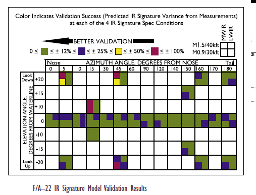
Hello! Can you tell me in detail how the IR signal was measured during the flight?
LikeLike
Thanks for sharing your knowledge
LikeLiked by 1 person
Helllo my family member! I want to say that this article is
amazing, nice written and include almost all important infos.
I would like to peer extra posts like this .
LikeLiked by 1 person
After reading this wonderful article I feel like i want to study aviation.. Hope to read more posts like this one, regards!
LikeLiked by 1 person
Can I just say what a relief to uncover somebody that truly knows what they’re talking about on the
internet. You actually realize how to bring an issue to light and make it important.
More and more people have to check this out and understand this side of your story.
I was surprised that you are not more popular since you most certainly possess the
gift.
LikeLike
This is my first time go to see at here and i am genuinely pleassant to read everthing at
one place.
LikeLike
Normally I do not read post on blogs, however I wish to
say that this write-up very forced me to try and do so! Your writing style
has been amazed me. Thank you, very nice article.
LikeLike
Thanks for the marvelous posting! I actually enjoyed reading it, you may be a great author.
I will be sure to bookmark your blog and will often come back from
now on. I want to encourage continue your great posts, have
a nice holiday weekend!
LikeLiked by 1 person
I’m not sure where you’re getting your information, but great topic. I needs to spend some time learning much more or understanding more. Thanks for fantastic information I was looking for this information for my mission.
LikeLiked by 1 person
Wow, incredible weblog format! How lengthy have you ever been running a blog for? you made running a blog look easy. The full look of your site is magnificent, let alone the content!
LikeLike